
I've had quite a lot of fun with the Novation Launchpad, building interactive MIDI sequencers and control surfaces. For a while I've had the idea in mind of making an Arduinome (an Arduino powered DIY Monome MIDI controller)
When I was working with Will Nash on the Noisy Table, I really got to like the micro-switched arcade buttons that we fitted to the table to control the sounds. And so it was I hatched a plan to make a Monome style grid controller using arcade buttons. I soon found it had been done before, but it looked so cool it just encouraged me more.
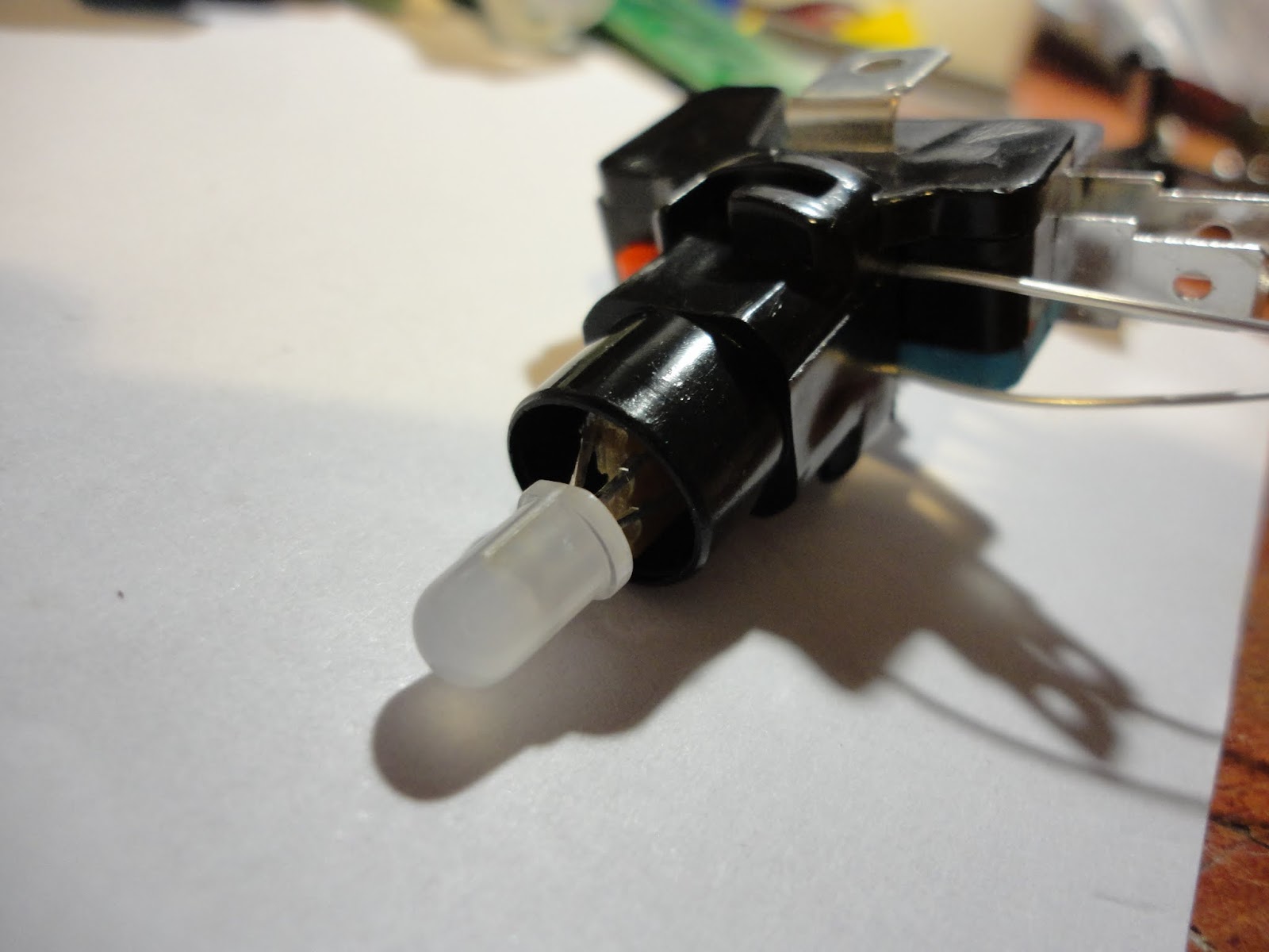
I bought the switches quite a long time before I really decided exactly how I was going to use them. They have translucent white plungers with an LED holder in the microswitch clip at the base. The supplied LEDs were white and resistored up for 12V (I guess as a drop in replacement for filament bulbs in arcade machines). I decided to replace them with RGB LEDs, but I needed to make sure I had a decent scheme for doing this, since I needed to wire up 80 of these switches and didn't want to end up making the same mistake 80 times!
 |
| 12V LED modules and sockets |
 |
| Microswitch heaven! |
What I ended up with was breaking a matrix board into little squares, so I could thread the leds of the 5mm RGB LED through the holes and slide the board into the socket in place of the white LEDs modules. This worked nicely to connect the common anode and one of the cathodes to the LED socket. I was then faced with somehow getting a connection through to the other two cathodes while not interfering with the operation of the switch.

I have a big roll of Kynar wrapping wire that comes in very handy for this kind of thing. Kynar wire is a single core wire with a very thin insulation layer, so it easily gets through the tiniest of holes and gaps. I could solder two wires to the remaining LED cathodes and thread them down through the socket and out between socket and switch. Since the thin single core wire can be brittle I used little blobs of superglue to anchor the ends after soldering (Its amazing how much more useful superglue becomes if you get a spray can of activator, which sets the glue off instantly - even in blobs)
I am driving my LEDs with LPD6803 chips, which I have a big batch of from an eBay bargain. These are chainable 3-channel, constant current, self-running PWM controllers with a 2 wire serial interface. They allow 5 bits per channel of PWM resolution (Maybe the 8-bit PWM WS2801 would have been better, but I think these LPD6803's are good enough, and they are what I had)
Every single LED needs its own controller chip... thats 80 chips... how to fit them all in? I considered putting an LED driver board on every button but quickly decided that wasn't going actually to make life any easier. In the end I decided to put 8 driver ICs on a PCB and have one PCB per grid column (so 10 boards). There would be a lot of wire in there, but it seemed the most straightforward way to build it.

I've recently started getting small batches of PCBs made up by a supplier in China (ITEAD), and these driver PCBs are only the second batch I have ordered. Just getting the thing wired up to see if it worked (or if I had badly messed up my PCB design) took a long time and the suspense was killing me - but finally I was able to connect up an Arduino to send some data to it... and it worked!!

As well as the 8 x LPD6803 chips the PCB contains a 74HC165 parallel input shift register for reading the switches. I wasn't going to count my chickens until I'd also tested the input part. Wooo, that worked too! (Eventually the input and output driver chips for all the boards will be chained together so the last test will be whether that all works)

The console for the grid is laser-cut 5mm acrylic. I had considered making a box completely out of acrylic, but wondered how sturdy it would be. Eventually I settled on building the box into a flight case and thought cases designed to house 19" rack-mount mixers would be perfect. The one I got is a Reloop case from eBay, where if cost about £75. Not the cheapest way of getting a housing, but it should be good for a few knocks.

So... looks like I have a lot of wiring to do! I am still not certain how I will drive it when its finished, but most likely I will use an Arduino.


