Wednesday, 1 February 2012

POV Digital Clock on 2.5" HDD Platter

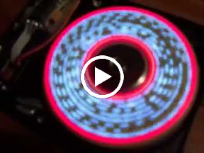
Just starting this project, which again uses a 2.5" laptop drive.

Last year I made a POV "slot" clock on a HDD platter, inspired by other peoples projects I saw online. Around the same time saw an excellent project on YouTube where someone had made a digital POV clock by spinning a set of digit-shaped windows, in front of a row of LEDs. By illuminating each LED when the appropriate digit was in front of it, a row of digits can be displayed... aka a digital clock (http://www.youtube.com/watch?v=7Qyawcw-ots)

That project used a 3.5" drive and it looked like the digits were actually laser or plasma cut into the metal platter itself. I decided to make an easier version by etching the digits into a piece of FR4 copper clad board to replace the platter. FR4 (the fibreglass PCB backing material) is quite translucent so it should transfer the light nicely from LEDs placed behind it.

So far I just have the platter made. I am using a 2.5" laptop drive and the space behind the platter is very limited, so I will probably place the LEDs on flexible kapton copper-clad sheet and put a row of windows cut in plastic sheet over the top to stop cross-illumination.

I'll spin the disk using the same TDA5144 circuit I used in the previous project but I'm not sure about indexing yet... there is not really space on the platter to cut a slot for a photointerrupter, and a magnet on the disk (for a fixed hall sensor) would need a counterweight and might not fit. I might try an IR reflective sensor here, but need to play with them a bit first as I've not used them before.

Keep ya posted!

POV Fun With 2.5" Hard Disk Drives

I picked up a few faulty laptop drives cheap on ebay to take to bits and use for POV projects. I haven't finished them yet, but have been tinkering over time and will post my progress as I go.

For the first one I wanted to put a row of SMD LEDs on the platter itself (or at least on a bit of PCB replacing the platter). The problem is powering the thing... I still need to play with inductively coupled coils for power transfer, but for now I decided to use batteries.

With CR1216's and 1117 regulator

I started with a couple of CR1216 cells in holders - they balanced pretty well when the disk span up and it didn't vibrate too much. Unfortunately when I built up the rest of the circuit I hit a problem.. the LEDs would start up fine but after a few seconds they had faded down to nothing. Fresh batteries - same thing.

CR1216's are 3V lithium batteries (putting out about 3.3V) so I had a 1117 5V regulator on board to give me 5V for the PIC16F688 and the LEDs. I wondered if the current draw was reducing the battery EMF right down below the drop-out voltage of the reg so basically nothing got through the regulator. However when I removed the regulator from the circuit exactly the same thing happened. I guess CR1216's just don't have the oomph for running these high power LEDs :o(

Then I removed the CR1216 holders and put a couple of LR44 holder in their places. LR44's are alkaline button cells at 1.5V and they are a bit bigger than the CR1216's so I worried a bit about their mass on the spinning disk, but it seemed I could get away with that and they didn't fly off or anything (well, maybe just the once..)

The other concern was the lower voltage. I would get 3V instead of 5V to power the LEDs, so would they light properly? They did :o) However, the 3144 hall-effect switch I was going to use for indexing needs 4.2V minimum so I could not use that. Therefore I am currently able to get some pretty, but not stable, patterns while I wait for some new hall switches to arrive (with 3V minimum supply).

With LR44's and reg removed
Once I have the new hall switch I should be able to index the position of the disk using a magnet fixed below it, then I want to display text on the platter. This is really a test... the PIC doesn't have the memory to do much and the batteries probably wont last that long, but I hope to make another with external power (either with a brush to the back of the platter - there is continuity through the hub which makes that easier - or by inductive coupling)

This clip shows it in action. The data is just a binary counter for something to display, but its pretty

From POV on laptop hdd platter


Sunday, 8 January 2012

Midi-izing the Reissue Stylophone


A while back I did a "midi conversion" of a couple of Stylophones (The original analog model). I did this by removing the Stylophone electronics and leaving just the stylus, keyboard and resistor ladder. Using the keyboard as a voltage divider its then possible to connect the stylus to an analog input of a microcontroller (such as Arduino) and read the analog voltage to work out which note is being touched, then send out MIDI note data accordingly.

There are a few problems with this approach:

  • The stylus, keyboard and resistor ladder need to be disconnected from the rest of the stylophone circuitry... Looking at the stylophone schematic the best I could do was a minimum of three connections to break. It wouldn't be possible to have the original sound at the same time as MIDI doing it this way.
  • As with any mapping from an analog voltage to a range of discrete values there is a risk that a bit of dirt or grime on the keyboard will add enough resistance to cause the wrong note to be mapped. Not good!
  • Original Stylophones are classic bits of kit and ripping the guts out of them doesn't feel right. Also they aint getting any cheaper.


Since I had a couple of "reissue" Stylophones I picked up on ebay I decided to see if they might prove a better bet for a conversion...

The first problem was getting inside the thing... while the old Stylophone closed with a clip-on back, the new one is glued shut and getting it open without breaking any of the plastic is easier said than done.

Expecting similar nasty cost cutting inside I was actually surprised to find how much is actually in these things. There are no less than four separate circuit boards all individually screwed down to the case and connected with wires (although they are crappy wires with joints that snap when touched)

Removing the boards from the case I found there is the obligatory chip-on-board "black blob" and a few SMD components on the main board. As I expected these new Stylophones do away with the analog tone generator circuit in favour of some custom chip that presumably digitally creates the sound. There is also a through-hole soldered amplifier board and separate carriers for the power/vibrato switches and volume pot.


Those chip-on-board blobs are usually heart-sinkingly unhackable and the sight of one usually spells the end of any thoughts of doing anything interesting. However I was intrigued to see that there was a separate trace from each keyboard pad to the blob, and checking the stylus I found it was wired directly to the +4.5V supply.... so could it be that we had a digital inputs line for each keyboard pad, with some pull-down resistance? That would almost be too good to be true... but true, it was!


So why is that good? well microcontrollers like the Arduino love to read digital (i.e. ON/OFF) inputs. These are nice and reliable without the dirty connection issues of analog inputs, but not only that, you can "piggy back" your inputs off the original input lines (since you are just reading a voltage, not drawing a current). What this means is that you can read the notes being played, while the Stylophone circuit is still attached to the keyboard and playing normally. Also you should be able to get an Arduino to actually play the Stylophone, by feeding ON (logic HIGH) values into the lines... but I might leave that till another day :)


Even better, the board has an exposed pads on each line perfect for carefully soldering a wire to. So thats the good bit. The bad news is that there are 20 of these input lines... thats a lot of wiring and is enough to use up all the inputs on a Arduino board...

I decided to use 74HC165 shift registers to read the keyboard and cut down the number of input lines needed. These chips each read 8 inputs then send the data out in a serial stream. By chaining these together, any number of inputs can be read with just 3 wires to the Arduino (one to "capture" then inputs then a "clock" and data line for reading the data).


Using fiddly surface mount components it was possible to fit 3 of these shift registers on a board that would fit underneath the Stylophone main board, keeping it out of the way and snugly held to stop it shaking around.


An Arduino Nano would fit in the Stylophone case, but I decided to use a custom SMD board since I wanted to add an KXPS5 accelerometer to detect tilt (for pitch bend). I also added another 74HC165 shift register to the chain for reading additional inputs from a row of tactile switches mounted to the back of the Stylophone. A 5mm RGB on the front allows a "mode" to be indicated.


And it worked... mostly. I am having some issues with the accelerometer which may be down to a bad connection (those things are a bitch to solder!) but the keyboard reading and MIDI is working pretty well. Hopefully it will all be finished soon. Watch this space!


UPDATE: I finally found out why the accelerometer wasn't working... even in analog output mode on the KXPS5 it is neccessary to set the "enable" input high only AFTER the chip is powered up (at least 1ms after). I had tied the enable input high on my etched board, d'oh! Failure to do this makes the analog outputs go mental... I only found this out after I decided to ditch my homebrew board and use an Arduino Nano in there. 

Saturday, 3 December 2011

Flashing LED Christmas Card Project

This is a DIY project to create a flashing christmas card based on a 555 timer. I did a project like this many moons ago at school, and when my local hackspace, Build Brighton, were thinking of seasonal electronics projects we could offer in workshops I decided to try to recreate this idea.

The circuit is a basic "astable" circuit (which simply means it oscillates between states). In this case we use the venerable 555 timer integrated circuit to make a square wave oscillator with a frequency of a second or two.

The output of the oscillator circuit goes to 0V, stays there a while, then flips up to 9V, stays there a while then flips back to 0V and repeats again. When the output is 9V it lights up a set of LEDs. The "clever" bit is that when the output is 0V a second set of LEDs light up, because those LEDs are already connected to 9V (i.e. "positive") on their other side, and get connected to 0V (i.e. "negative") when the output of the oscillator goes down to 0V. The end result is that the two sets of LEDs flash alternately.

I found a small current flows even between the "high" output of the 555 and the 9V supply, so the LEDs are never completely off but flash from dim to bright (but in some ways that looks even nicer :o)

The parts needed for this project are

8 x identical "standard" LEDs
1 x "standard" LED for top of tree (can be same type as above, but you might want a different colour)
9 x 220 ohm resistors for the LEDs (typically 220 ohms but you might want to experiment with higher or slightly lower values to get the brightness levels you want. I used 100 ohm resistors on my red LEDs and a 470 ohm on the blue led)
1 x 555 timer IC (e.g NE555)
1 x 10M (10 mega-ohm) resistor
1 x 470k (470 kilo-ohm) resistor
1 x 10nF (0.01uF) ceramic capacitor
1 x 100nF (0.1uF) ceramic capacitor
1 x PP3 battery snap connector
1 x PP3 battery
Some connecting wire (e.g. 1 meter or less of thin equipment wire)

You can build this by poking the component legs through holes punched in the card, then soldering them on the back. This is kind of fiddly but it wouldn't be quite the same end result to build it on a board.

The following diagram shows the connections from the INSIDE of the card (i.e. the side you see when soldering). Click to enlarge
When putting the 555 IC on the card make sure that you insert it through the front of the card with pin 1 at the top (the end of the chip with pin 1 will be marked with a notch or dimple).

The LEDs must be inserted the right way round for this project to work. The anode (+) side of the LED is marked by a longer leg and the cathode (-) has a flattened edge to the lens. Use the + symbols next to the LEDs in the diagram above to make sure you put them in the right way round and remember the diagram shows the BACK of the circuit!

The resistors and capacitors have no specific polarity and can be soldered either way round.

Don't heat components for too long when soldering. LEDs are particularly sensitive to overheating and it probably won't do the 555 a lot of good either. It helps to bend leads together (so they stay joined by themselves) before soldering so you can be quick with the heat.

My card was particularly utilitarian, but I'm sure you can make it look much nicer :) sticking a sheet of card over the wiring hides the mess and strengthens it all. It would be good to see other peoples results!


Saturday, 5 November 2011

Lost in Maths! (2D Sound location with 4 sensors)

This post is about my ongoing project to do fast 2D sound location on a ping pong table, this is some ideas I've been having and wanted to share - since I need some help!

Ok here's the problem... we have a rectangular area ABCD and somewhere in that area (point X) there is an event that produces a sound (e.g. a ping pong ball strikes the surface). This results in sound waves travelling outwards to the corners where they are picked up by sound detectors.

The first sound to be picked up at each sensor arrives at a time that obviously depends on that sensor's distance from the original sound. Lets call the times tA, tB, tC, tD. (Each sensor will pick up reverberations and echoes after the original sound, but its the first "edge" of the sound we're interested in)


Now since we don't know when the original sound happens (we only detect it when it got to the closest sensor) we don't actually know the real values of tA, tB, tC, tD but we get relative times from the first sensor. In this case X is closest to D,  the sound reached D first. The time we read at each sensor A,B,C is relative to tD. Graphically this can be shown like this (each red line is reduced by distance XD)


Now we can use these reduced distances to define circles based on the points A,B,C and D (radius at D is initially zero)

As pointer out by Arduino forum member Necromancer on http://arduino.cc/forum/index.php?topic=52583.0 we can find X  geometrically by progressively increasing the radii of the circles at A,B,C and D by the same amounts until all the circles intersect at a single point. At this point we have added back the unknown distance XD and the circles intersect at point X as shown below.


The problem is that this iterative calculation of circle intersections is processing-heavy and would probably take too long to solve on a microcontroller to be responsive enough for my application. However I started thinking about getting a "head start" by doing some simple calculation to get the initial increment where all the circles intersect for the first time, and go forward from there.

Here's what I mean.... point Q is a point on the line AC which is equal distances from the points where the initial circles around A and C cross AC.


The actual coordinates of Q aren't needed, we just need to know how much to increase the radii of the circles around A and C so that they intersect at the first time (which will happen at Q)


The calculation is simply the length of AC minus the radii of the two circles, all divided by two. If we calculate this value and add it to the radii of the circles they will meet at Q.

If we do the same calculation for lines AB, BC, CD, AD, AC, BD we'll get 6 different values that we should increase circle radii by make them intersect. We can just take the largest of all the 6 values and apply that as the base value by which the radii of all the circles should be increased to get to the initial point where all the circles intersect.

This will not neccessarily be  point X... we might need to interatively expand the circles a bit more to make them all intersect at the same point. However we got a big head start and so far we've just done simple arithmetic.

I made a simple program where I could click with the mouse to simulate the values arriving at the 4 sensors., then applied the above calculations... in many cases the results are very close to the final point X. For example:


In other places the accuracy is not so spot-on, but it looks like some kind of simple averaging of the points of intersection might give a position good enough for what I want, and without having to iteratively apply complex calculations (like square roots), so it should be pretty fast.


Only three sensors are strictly required for multilateration, however I found that adding the fourth sensor made a massive difference to the accuracy of the above calculation.

The next step is to calculate the points of intersection and give it a try with some averaging, to see if I can avoid the iterative method. However I'm not a mathemetician, so if anyone has a better idea, please let me know!

Update: OK, I gave the averaging thing a try. This clip shows my test program using these calculations to track the mouse pointer. The tracking is not perfect and there are a couple of places (vertical midpoint of the area, towards left and right side) where it is worst, but I think this is good enough (especially given that my sensors won't be perfect!). 

The program displays the fours circles calculated as above. The final calculated position is displayed by the red crosshairs


The process is as follows:

1. Firstly I need to simulate the sensor inputs, so I take the position of the mouse pointer, calculate distance to each corner and then subtract the minimum distance from all the others. The results (tA, tB, tC, tD) are representative of time or arrival info from real sensors.

2. For each edge, and the two diagonals I get the length of the line (area width, height or diagonal distance) and subtract the relative arrival times for the points at each end. 

offset1 = (width - tA - tB)/2
offset2 = (width - tC - tD)/2
offset3 = (height - tA - tD)/2
offset4 = (height - tB - tC)/2
offset5 = (diagonal - tA - tC)/2
offset6 = (diagonal - tB - tD)/2

Now take the maximum of these 6 values:

offset = max(offset1,offset2,offset3,offset4,offset5,offset6)

now calculate the circle radius by adding the offset to each time.

rA = tA + offset
rB = tB + offset
rC = tC + offset
rD = tD + offset

now calculate the intersection points of all pairs of circles. I used the C code example from here  http://paulbourke.net/geometry/2circle/

There are six pairs of circles, AB, AC, AD, BC, BD, CD. Not all may intersect (ignore pairs which do not intersect). Otherwise we get 2 insection points (which may be identical if circles just touch) for each pair of circles. Lets say that for each pair of circles we can get two intersection points P and P'

For each pair of points P and P', one will be closest to our target point and the other should be discarded. The way I did this was to calculate the average of all the points, then go back through the list selecting the point from each pair that was closest to the calculated average point and then averaging just these "closest points". 

ie. Take the first "rough" average of all points P and P' - lets call is (Xave, Yave), then recalculate the average position using either P or P' from each pair based on the condition:

if (Xp - Xave)^2 + (Yp - Yave)^2  > (Xp' - Xave)^2 + (Yp' - Yave)^2 
then use point P' 
else use point P

The resulting average (X , Y) is the final calculated point.

Better accuracy would be got by interatively increasing rA, rB, rC and rD and recalculating the intersection points until they are at their closest to each other. However I don't think I need this - the sensor input is unlikely to be so accurate it would benefit from this.... and I think it would be computationally expensive due to calling sqrt( ) many times and therefore slow.

Once again I'm no mathematician and I'd be grateful for any advice here!

Wednesday, 12 October 2011

Musical ping-pong tables and 2d multilateration

I'm currently trying to help out a local artist who is building an Interactive Ping-Pong Table, where each bounce of the ball generates a musical sound which depends on the position of the bounce.

I thought it should be possible to do this without drastically changing the table (i.e. without chopping the surface up) by using 3 piezo disks and an Arduino or PIC to time the arrival of the pulse at each disk and work out the position of the ball. It all sounded pretty easy, and an interesting project. Its certainly been interesting, but I'll think twice in future before deciding something is easy before I've properly thought  it through :o)

I found pretty quickly that some kind of amplification is needed.. the piezo disks are pretty sensitive to a sounds close by but not so great for something the other end of a table. First of all I tried to boost the level using 4069 inverter chips (I got that idea from Nicholas Collins' book - Handmade electronic music) since I've never really understood op amps and didn't want to get into all that dual supply rubbish. In my initial circuit I used an NPN Darlington transistor on the output of the amplifier stage to generate the logic pulse.

It kind of worked, but I was finding that the MCU would hang when an interrupt-on-change interrupt was being fired by multiple sensors. I also had a problem with the output getting stuck on (I think this might have been due to supply noise, noise picked up on a long wire to the piezo, and an overly sensitive amp stage). I  think the hang thing might have been due to noisy outputs triggering a rapid train of interrupts than the poor PIC could not handle. I have an IKA Logic analyser and using this I could see a mad train of pulses coming from sound waveform, echoes, supply noise whatever... I don't really know, but the PIC didn't like it.

Searching about for ideas online I read about running op-amps like LM358 from a single supply, which seemed to be a better way to do things than using logic chips as amps. I also saw how a 555 monostable circuit can be used to clean up a dirty pulse by keeping an output high for a timed period as soon as the first edge of the input pulse comes in, so the train of pulses from reverberations and so on get masked by a nice clean extended output pulse... nice and friendly for MCU interrupt pins.

The resulting circuit seems to work pretty well, even though it still seems a bit complicated. Maybe it is a case of over-engineering, but I learned a lot and it does at least work pretty well. Using SMDs I can also get it on a board about the same size as the piezo disk so it can sit on top.


For some reason I thought the maths behind working out a point from timing would be easy..and it is in one dimension with 2 sensors...


However working in 2 dimensions with 3 sensors seems to be a completely different kettle of fish... the technique is called Multilateration and there have been entire research papers written about it :o) The problem is that all the timing readings you're working with are relative... its more complicated than I  thought to get back to an actual position. Maybe I can simplify things, since my sensors will be arranged in the corners of a rectangular area and I can always calibrate them at the start by tapping the corners of the table. Or maybe some dirty trial and error approach will be good enough... Anway thats the next step... wish me luck..!

Here is the source code used in this clip

// SOURCEBOOST C
// PIC16F688
#include <system.h>
#pragma DATA _CONFIG, _MCLRE_OFF&_WDT_OFF&_INTRC_OSC_NOCLKOUT
#pragma CLOCK_FREQ 8000000

#define SENSEA            0b00010000
#define SENSEB            0b00100000
#define SENSE_MASK        (SENSEA|SENSEB)

typedef unsigned char byte;

// INITIALISE SERIAL PORT FOR MIDI
void init_usart()
{
    pir1.1 = 1;    //TXIF transmit enable
    pie1.1 = 0;    //TXIE no interrupts
    
    baudctl.4 = 0;        // synchronous bit polarity 
    baudctl.3 = 1;        // enable 16 bit brg
    baudctl.1 = 0;        // wake up enable off
    baudctl.0 = 0;        // disable auto baud detect
        
    txsta.6 = 0;    // 8 bit transmission
    txsta.5 = 1;    // transmit enable
    txsta.4 = 0;    // async mode
    txsta.2 = 0;    // high baudrate BRGH

    rcsta.7 = 1;    // serial port enable
    rcsta.6 = 0;    // 8 bit operation
    rcsta.4 = 0;    // enable receiver
        
    spbrgh = 0;        // brg high byte
    spbrg = 15;        // brg low byte (31250)    
}

enum {
    READY,
    LISTENING,
    TIMING,
    TIMEOUT
};

byte remaining;
long timeA;
long timeB;
byte state;

void interrupt( void )
{
    // check for interrupt on change
    if(intcon.0) // IOCA fired
    {
        // are any of the signals we're waiting
        // for now ready for us?
        byte savePortA = porta;
        byte whichSensor = savePortA & remaining;
        unsigned long thisTime;
        if(whichSensor)
        {
            if(state == LISTENING)
            {
                // start the timer
                t1con.0 = 1;
                thisTime = 0;
                state = TIMING;
            }
            else
            {
                // grab the current time
                thisTime = tmr1h << 8 | tmr1l;
            }
        
            // Grab times from sensors
            if(!!(whichSensor & SENSEA))
                timeA = thisTime;
            if(!!(whichSensor & SENSEB))
                timeB = thisTime;
                
            // clear bits for the sensors we 
            // already have
            remaining &= ~savePortA;
            if(!remaining)
            {
                intcon.3 = 0;            // ioca off
                state = READY;
            }
        }        
        
        // clear interrupt fired flag
        intcon.0 = 0;
    }    
}
        
////////////////////////////////////////////////////////////
// SEND A MIDI BYTE
void send(unsigned char c)
{
    txreg = c;
    while(!txsta.1);
}

////////////////////////////////////////////////////////////
// NOTE MESSAGE
void sendNote(byte channel, byte note, byte value)
{
    send(0x90 | channel);
    send(note&0x7f);
    send(value&0x7f);
}
void main()
{ 
    // osc control / 8MHz / internal
    osccon         = 0b01110001;
    
    
    // comparator off
    cmcon0         = 7;                      
    
    // configure io
    trisa         = SENSE_MASK;                  
    trisc         = 0b00000000;              
    ansel         = 0b00000000;
    porta        = 0b00000000;
    portc        = 0b00000000;

    // initialise MIDI comms
    init_usart();

    // 
    t1con = 0b00000000;
    
    // interrupt on change porta.4
    ioca = SENSE_MASK;
    intcon.7 = 1;
    intcon.3 = 0;
    intcon.0 = 0;

    byte note = 0;
    for(;;)
    {
        // Prepare to listen
        timeA=0xffff;
        timeB=0xffff;
        remaining = SENSE_MASK;
        state = LISTENING;
        t1con.0 = 0;            // reset the timer
        tmr1h=0;
        tmr1l=0;
        intcon.3 = 1;            // ioca on
        
        // wait to start timing
        while(LISTENING == state);
        
        // wait to complete timing
        while(TIMING == state)
        {
            unsigned long timeNow = tmr1h << 8 | tmr1l;
            if(timeNow > 0x8000)
                state = TIMEOUT;
        }
        
        if(TIMEOUT == state)
        {
            // ignore the interrupt if it does 
            // not register on all the sensors
        }
        else
        {
            long x=0;
            // i know i'm getting reading of up to 5000 'cos I printed 
            // them to serial port... you might get something different
            if(timeA > 5000) 
                timeA = 5000;
            if(timeB > 5000) 
                timeB = 5000;
            if(timeA) 
                x = 5000 + timeA;
            else if(timeB) 
                x = 5000 - timeB;
            if(x)
            {
                note = x/100; // is is in range 0-10000 so move this to MIDI range 0-100
                sendNote(0, note, 127);
            }
        }
        
        // delay (I think delay_ms function needs timer1)
        int i=1000;
        while(++i);        
        if(note)
        {
            sendNote(0, note, 0);
            note=0;
        }
    }
}

Monday, 12 September 2011

POV message fan project update


Got a bit of time this evening to test out the LED array I made yesterday for the Build Brighton message fan..


The thin wire-wrapping wires are soldered to a scrap  of veroboard for test connections , and the code is running on a PIC16F688. The shift regs are wired to share common clock lines, but each has its own serial data line, so all LED data can be loaded in 8 clock pulses so refresh should be nice and fast in the final thing.

Everything seemed to work first time, amazingly! These water clear RGB LEDs are nice and bright, but its possible to see the individual red/green/blue elements more than you would in a diffused LED (e.g. when you display yellow you can see the red and green elements rather than a single yellow point). I'm hopeful this won't be a problem when the thing is spinning and viewed from a distance.

My 100 ohm series resistance is rather low when the LEDs are run continuously but in the past I've found a low-ish resistance like this to be good when pulsing the LEDs quickly in a POV display. Still - I'll have to try to make sure the LEDs dont get left on 100% duty for a long time just in case they don't like the current.

I also mounted the board to the fan! With the help of some heavy duty double sided tape (for sticking carpets down) and cyanoacrylate superglue to hold the LEDs in the holes it seems to be pretty sturdy... famous last words...

Next step is to build a microcontroller board small enough to fit into the hub of the fan, then we (me and the Rev's Neil and Dave from BuildBrighton) need to get it power (via a pair of coils) and data (hopefully a modulated signal riding on the power)... and so the fun will really start!