This is the third post in my diary of building my "Hammer Pong" game.
After a visit with the kids to a local fun fair a couple of weeks ago, I thought some
fairground-style lights would look good to jazz up the fascia of my game! I started looking on eBay for used ones, but eventually
decided to buy some new ones.
Loads of LED stuff :o)
At first I was thinking of using a row of individual lights to mark the score, but then I got this crazy
idea of making a giant 2 digit, seven segment display!
First of all I needed
some kind of board to attach the display to for a proof of concept. My neighbour was
throwing out a big sheet of cardboard from a packing case, so I was
happy to take if off his hands.
These lights use LED modules in place of filament bulbs, which give a nice clean white light behind the coloured plastic lenses. The LED modules run on
24V and are rated for 1.2W which means they only need 50mA current,
which isn't too challenging to switch.
Bits of a light
I decided to use 3 light units
for each segment of my display, so for each segment I'd be switching 150mA at 24V. For
this I went for TIP120 Darlington power transistors as I had a few of
them lying about and I know them pretty well.
I wanted to keep my
options open for PWM fading and thought that if I used FETs I
might need additional FET driver ICs to PWM switch the FETs. Anyway, a bit of
experimenting on breadboard shows that a TIP120 could switch and PWM
fade a set of 3 lights, wired in parallel, without breaking a sweat.
For that test I connected the base of the TIP120 to a PWM pin of an
Arduino Uno, via a 1k Ohm resistor. The TIP120 switches on the low
side, so my lights were wired to the +24V line and their GND line was
connected to the TIP120 collector, with the emitter connected to the
GND of the 24V supply. Applying a voltage to the base makes the lights come on.
Now, I don't want to have to
use an Arduino pin for every one of my display segments, so I decided
to use a 74HC595 shift register to control the lights for the seven segment display. One nice feature of the 595 is
the Output Enable pin. Usually I hard wire this to ground to
keep the outputs enabled, but here I have it connected to a PWM pin
on the Arduino. I thought this would let me fade the brightness of
the entire 7 segment display and it seems to work superbly - just
need to remember it is an active low signal, so analogWrite(0) is
full on and analogWrite(255) is full off.
Each output of the
74HC595 is connected via a 1K resistor to a TIP120. Add a bit of code
to load the shift register, define the numeric digits are we're ready
to roll with a 7 segment display test!
Shift register/TIP120 driver board
The lights use a
screw-on base which forces some sharp terminals through the
insulation of the cabling. This makes it nice and quick to wire up
without soldering. I used a common 24V supply rail and wired together
the ground connections of the three lights on each segment, then
connected to the appropriate TIP120 collector terminal. A quick
Arduino sketch and I have digits counting, with a bit of a fade in
and out around a change of digit.
Quick'n'dirty build
I think I made my digit
a bit tall for it's width, but the visual effect seems to work. Now I
just need to make sure I have enough space on the fascia of my game
for 2 of these - they are quite big! I hope they aren't too big to read properly from a playing distance... hmmmm.... only one way to find out.
The next step in the build of my Hammer Pong game was to read the user input - when they whack something with a big ol' hammer.. I wanted to give the
game some kind of “velocity sensitivity” so that different levels
of force would trigger different behaviours in the game (but maybe a
very hard hit would not always be to player's advantage - perhaps if
the opponent manages to return a fast shot it comes back at
ridiculous speed:)
Since I can see this part of the build taking a lot of punishment, I wanted to avoid
anything with moving parts that were likely to break with prolonged
use. My idea was to use a piezo disk as a contact pickup, and design in some way to detect the force of a hit (tell the difference between
different volume levels). For robustness and safety reasons I thought
using a foam hammer with a foam block as the target. Burying the
piezo disk deep in the block should protect it.
I'd seen the EVA foam
blocks that are sold by gym shops as exercise aids and thought they
would be good to try, being pre-shaped and finished, tough and quite
dense with a small amount of “give” to them.
I had originally
anticipated getting some kind of off-the-shelf toy hammers, made out
of foam or rubber, but I could not find anything that looks very suitable.
Most of them were very soft light foam, too small, or inflatable, so
I decided to try and make my own using EVA foam blocks. For the
hammer handle I bought some fibreglass broom handles (thinking they
would be lighter and safer than wood, but still hold up to some
abuse).
I still need to give
the construction of the hammers some thought, but for my tests I used
an EVA foam “yoga block” as the head and a length of broom
handle. I used a standard holesaw, intended for timber, to bore a
hole into the side of the block (I fully expected it to rip the foam
to pieces, but it actually cut the cylindrical hole perfectly!).
Again still experimenting I used generous amounts of cyanoacrylate
superglue (set off with activator spray) to join the handle to the
head. Superglue is brittle, so I thought it might crack with use, but
I tried very hard to break it by hammering things or shear it by
twisting the handle... suprisingly the glue join held up to all the
abuse I gave it so there is definite potential.
Hammer Prototype
I wrapped the piezo in duct tape and buried it in the middle of an EVA foam cylinder. The only downside is
that the “slap” of the two foam surfaces hitting each other is
very loud.. maybe too loud. I might experiment with covering the
target with fabric later on..
Foam Cylinder With Piezo
So on to the
electronics... I know from experience that a piezo disk can throw out
a pretty high voltage spike if you hit it hard. Since I wanted to be
able to get a measure of how hard the target was hit, I had to use
an analog measurement of the piezo output voltage. But, now the
microcontroller I am using runs at 5V power, any input voltage higher
than 5V would be clipped at 5V on my analog input (I could use a
higher analog reference voltage, but lets keep it simple) reducing
the range of input levels I can tell apart so middling hits and hard hits would be indistinguishable.
So, I need some kind of
attenuation (scaling down) of the input voltage level, for which I used a simple 10k trim pot. I also thought some low-pass
filtering would help separate the main impact impulse from other
noise. Something else I noticed with an oscilloscope was that the
negative voltage peak coming from the struck piezo was substantially
higher than the preceding positive peak (not sure why that should
be..).
Anyway, all of the factors led me to using an op-amp to make an active lowpass filter (which also inverts and buffers the input). The trimpot gives a variable
attenuation of the raw piezo output to bring it within the range of the opamp input. The opamp output can then be fed directly to an
analog input pin on the microcontroller where it can be measured.
While I am planning to
use an ATMega328 for the main processor on this project, I decided to
offload the input monitoring to a second MCU, I think this is particularly important given the main processor could be blocked for a short time updating the LED strips and might possibly miss input pulses. I used a PIC16F1825 for my little helper as
I am familiar with this chip and have a ton of them.
Circuit On Stripboard
My PIC code monitors
two analog inputs (one for each hammer target) in parallel. When an
input reading exceeds a trigger threshold, the PIC samples the input
over a short period, storing the maximum value (the idea
being to get the peak value of the trigger pulse). This information is then
transmitted as a serial message and the
PIC waits holds off for period of time to allow the sound to fade
before going back to listening. See the code here https://github.com/hotchk155/HammerPong/blob/master/InputListener/InputListener.c
I used MIDI for the
serial protocol. Some people might say I use MIDI for everything,
but I love it for a lot of sensible reasons :)
- It is very simple to
implement, with most messages being only 3 bytes long
- It has a nice easy
synchronisation scheme (bit 7 set means start of new message - simple
as..) that stops your sender and receiver getting out of step
- It is perfect for
this kind of thing (transmitting simple “note” events with a
velocity) - it is pretty much what it is designed for.
- The best bit... if
you have some MIDI gear and utilities then you already have all the
test tools you need! I can test my input reader before I have the
main game program written by simply playing notes through a
synthesizer. When I test the game I can fake input using a MIDI
keyboard. And I already have a bunch of MIDI cables I can used to connect things together.
My 1-D Pong game was accepted to be part of an electronic art exhibition this summer.. Yay!! 1-D Pong was a project of mine from a couple of years back, which uses a 5M addressable LED string as the display surface for a game based on the classic PONG. Since the LED string is one dimensional, you can't "miss the ball" in the conventional sense so the gameplay is all about timing; you press a footswitch at exactly the right moment to return the ball. Despite being so basic it works pretty well as a game, and the pace accelerates with each return to keep it challenging.
As this will be my first gallery installation I decided I really wanted to improve and build on the original (which is, to be honest, getting a bit tatty) and do something a bit more ambitious. In speaking with the curator a few weeks back I learned that the venue has a 7 metre high ceiling, and that the exhibition would have a fairground theme. Wouldn't it be great to orient the 5m strip vertically up the wall, I thought. That got me thinking about those old "high striker" / "test your strength" fairground side shows.. you know the ones with the big hammer to whack a puck up a tube and ring a bell? Well.. combine that with the 1-D Pong and Hammer Pong was born!
Two players will whack it out against each other, hitting their foam mallets against foam block "triggers" to shoot a pulse of light up a vertical LED strip, where it will cross over and return down the opponents strip. The opponent needs to hit their block at just the right time to fire the pulse back as it reaches the base of the strip. Miss the timing and you lose.
A simple concept, but technically a little bit more challenging build than the original 1-D Pong. I will be building it over the next few weeks and will post my progress on this blog, which might be of interest to anyone who wants to know about the build after it is complete. So let's get started...
Challenge number one is that I need to drive multiple LED strips. My original 1-D Pong project was created a couple of years ago when addressable LED strips were new (and rather more expensive) and my strip used an obscure controller called a yds600 for which I had to write my own support library. Due to the way the strip required the SPI communications clock to keep "ticking" after the data was latched, to keep its PWM going, those strips would be hard to drive in multiple.
However, these days most strips use the WS2812 controller - I find these things amazing; the controller chips is actually inside the LED!!
Just think about that for a moment... a single WS2812 LED is a tiny package about 5mm square, containing not just red, blue and green LED elements but a tiny silicon chip with a serial data controller, internal oscillator, three 8 bit PWM channels and current management circuitry. They can be had for less than 20 cents each but are more usually bought in flexible strings (usually 30 or 60 LEDs to a metre) where the LED data in and data out pins are chained together as a giant shift register so a single data pin on your microcontroller can drive them all. I think that's amazing!
Also, these days it is easy to find ready made code to drive the strips. Adafruit sell WS2812 LED assemblies under their NeoPixel brand and their Arduino library code seems pretty well written, so I have been working with that. One potentially nice point about the Neopixel library code is that it "bit-bangs" the data (the output pin is explicitly toggled on and off by code rather than using a built in serial hardware peripheral on the AVR) so the strip is not confined to specific output pins.
This means that two strips could be connected to different output pins using the NeoPixel library. However I was already getting a bit more ambitious than that... when I bought my strips I bought a job lot of ten x 5m WS2812B strips with 30LEDs/m so I could get the price down to just over US$30 a strip including shipping from China. This means I have quite a few strips to play with :)... so why not make each of my 2 players "tubes" actually made up of 3 LED strips side by side, giving each a 3x150 pixel matrix to allow some simple animations and effects, and increase the brightness... Oooh!
Ten 5 metre addressable LED strips
To run the total 6 strips needed I could use 6 output pins and 6 instances of the NeoPixel library object, or I could potentially chain the strips together and use a single pin by treating them as a single 900 (150 x 6) pixel strip. However, I think this would mean the library keeping an image of the 3 byte colour data for each of the 900 pixels in memory at the same time, which would not even fit in the Atmega328's 2k of RAM!
So... I need to be a bit creative. Firstly there isn't really a need in my game to keep an image of the display contents in memory.. All the required display content can be recalculated at every frame then dumped to the strips and latched into them. There is no need for me to refer back to the display content afterwards (e.g. collision detection is not relevant).
Also the WS2812 data protocol is very timing critical, so the transmit code needs to be tight and run without interruption (I am pleased to see Adafruit coded the important parts in assembly language in their library). This means that it is not possible to send data to multiple strips in parallel, you must send the full set of data to each strip in turn (unless they are chained together and a single send can address all strips, but this needs the full 900 pixel content to be buffered for send, so is a no-no)
So, I decided I need a way to update one strip at a time, making sure I required only a single 150 pixel buffer in memory. I guess two options are possible
Dynamically reconfigure the NeoPixel library to direct the data from a single library object and 150 pixel buffer to 6 different digital output pins in turn, re-rendering image into the data buffer for each new strip. This would need to use 6 output pins. It may also need some changes to the library code to allow the output pin to be efficiently reconfigured on the fly.
Use a digital multiplexer IC (I have some TC4514BP's available, which should fit the bill) to connect a single output pin to each of the 6 strips in turn, re-rendering image into the data buffer for each new strip. This would need to use 4 output pins (one for the data and 3 for the selection between strips). I'd need to make sure the multiplexer chip would not skew the output pulses (which for the WS2812 are timing critical). I thought this approach could work without changes to the library code, but read on...
I went for the second option... some simple tests on a breadboard showed it worked, but I did need to modify the NeoPixel library code to allow the data output to be inverted (so that when it would usually output HIGH it output a LOW and vice-versa). I'll explain the reason...
The 4514 digital multiplexer has 16 outputs (more than I need, but I have a load of these chips lying about so..). You have 4 Address pins which you use to select which of the 16 outputs will be set to a HIGH value (all the other 15 show LOW).
There is also an Enable pin which must be held low for the selected output to show HIGH. If the Enable pin is HIGH then all of the 16 outputs are LOW. This allows the Enable pin to be used to toggle the selected output pin between LOW and HIGH, BUT the logic is inverted. If you want the selected output to be HIGH then Enable must be LOW and vice-versa. Therefore if we want the output from the NeoPixel library to drive the Enable pin we either need some kind of Inverter chip, or we can hack the library code to enable inverting of the logic. I went for the second option :)
TC4514BP 1-of-16 Digital Multiplexer
Some simple tests on breadboard and it seems to be working fine. I was concerned about the gate lag on the multiplexer impacting the time-critical WS2812 protocol (ICs have a small but possibly significant "propagation delay" between changing an input and seeing the output change) however as long as the delay is symmetrical and rising and falling edges are delayed by a similar amount of time then it should not be a problem for my application. The data sheet shows this is within the WS2812 +/-150ns tolerance.
Another good thing about this multiplexer is that unselected outputs are driven LOW rather than floated. This means that the WS2812 "Latch" command (pulling the data line low for an extended period of time) can take place after we have deselected the strip and moved on to the next one, making things ever so slightly faster.
Simple test with 2 strips
In case you want to use the same approach, here is the change I made to the NeoPixel library. First off I added a flag field activeLow (I wanted to make it switchable in case I needed to toggle during trouble shooting)
class Adafruit_NeoPixel {
:
private:
#ifdef __AVR__ uint8_t activeLow; // Set to 1 to use ACTIVE LOW output pulses
The library implementation uses conditional compilation directives for the many Arduino boards, so you need to look through and find several places where the bit masks lo and hi are defined. This is a pre-calculation of values used later to toggle specific bits in the port registers. hi is usually set to the current port value with the target bit set and lo to the value with the bit cleared. We simply calculate these in the opposite sense if activeLow is needed
if(activeLow) { lo = PORTD | pinMask; hi = PORTD & ~pinMask; } else {
Someone sent me this clip and wow, what memories came flooding back.
Ant Attack on the ZX Spectrum was the first computer game that not only totally hooked me, but made me think "I wanna be able to do that". At one point, circa 1984, I could even beat the "hall of fame" high scores published in Personal Computer Games (PCG) magazine, though I was much too shy to write in about it.
One of the dubious joys of the Spectrum was getting to actually hear programs loading. Games could take upwards of 20 minutes to load from cassette tape - which meant you made damn sure you made the effort to enjoy them - and as they loaded you could hear the whistles, chirps and drones of the bits and bytes of game code.
Every game had its signature loading sound and I can still immediately recall the last few clicky seconds of Ant Attacks loading before it launched into the beepy tune that accompanied the blocky title screen.
Ant Attack was my first hacking experience. I worked out how to break into the tape loader and get access to the BASIC program that controlled the machine code routines, then I started messing with it to move things about about, such as the characters you're supposed to rescue (the positions were all coded in DATA statements in the BASIC code)
I moved on to searching through the programs memory image, looking for the data for the "city" that was the game area, then printing it out in long strips on my Alphacom 32 toilet roll printer and sellotaping them together into a map which I proudly blu-tacked to my bedroom wall.
Some 10 years later I created my own version of the game for the PC, written in C and inspired by a superb Manic Miner port. I found a cassette tape image file for Ant Attack somewhere on the early internet and tracked down and pulled out the bitmaps for the game graphics and the city map. I got the movement and display routines all working but unfortunately didn't get the game play finished off :-(
Anyway it was a joy for me to see this interview with Sandy White, the creator of Ant Attack. i had no idea what he even looked like before seeing this, and I only remember his name from the big "(C) SW" laid out in bricks on the city map in the game, which I remember noticing when I printed out the map.
I was pleased to see Sandy White HAND ASSEMBLED all the machine code for the game.. now this really does bring back memories as I used to do this myself, on a much simpler scale, armed only with the list of Z80 assembly language instructions that were printed alongside the character set at the back of the ZX Spectrum manual. Top stuff! Hey I even used to hand assemble Z80 machine code without a reference list, just by remembering all those opcodes from looking them up so many times. I really should have got out more.
Since I made my first Arduino-powered MIDI arpeggiator a couple of years back I have been meaning (and promising) to get a kit together so others can build their own. Today I listed my first "fundraiser" on Tindie. Hopefully that will raise enough cash get the PCBs made up for 50 of these little beasties!
These ARPIE kits are made up of 2 PCBs which stack up with 25mm standoffs and connect together using a 2x10 way long pin header strip, so there are no ugly wires. The top board is the control surface, packed with 29 tactile switches and 20 LEDs which together provide all the user-interface you get (or need)
I wanted to preserve the look of my original arpeggiator build, which was in a bright yellow case with black Dymo embossed tape labels. I went for a "Dymo" feel to the PCB silkscreen in this latest build. I made them up in a drawing package and imported them into EAGLE as .bmp files. Although my initial prototype PCBs are standard PCB green, I hope to go for bright yellow soldermask (boards) and black silkscreen (text) in the production run.
On the back of the control surface PCB are two 74HC595D surface mount shift registers. When I release the kit I will solder these myself, leaving just the easier through-hole stuff to be added.
The shift registers are used to scan the switches and drive the LEDs so that only 5 digital I/Os (3 ouputs and 2 inputs) are needed to drive the sixteen blue LEDs and poll the sixteen 6x3mm "Data Entry" tactile switches and the twelve 6x6mm "Menu" tactile switches. The low side of the LEDs is controlled by a 2N3904 transistor. By switching an LED on then off "early" in its refresh cycle we can get multiple brightness levels.. a kind of "poor man's PWM". The scan cycle is controlled by a timer interrupt.
Although there is no actual Arduino board used - this is an Arduino project - with Atmega328 and 16MHz crystal on board. As with most Arduino projects, all the clever stuff happens in the firmware. We send MIDI simply using the Serial port (31250 baud rate). The MIDI spec tells us to optically isolate the serial input to avoid possible grounding issues between equipment so a 6N139 opto-isolator IC sits on the MIDI input.
A feature of the ARPIE is to be able to "slave" to a MIDI SYNCH source which is different to the MIDI input where the notes are being received. For example we might have a keyboard on MIDI IN but want to get our SYNCH from a drum machine.
MIDI SYNCH is achieved through special "tick" messages which arrive at a MIDI input in real time (24 ticks for every beat) so we need a second serial interface to receive these. Since this is rather crucial for timing synchronisation, rather than "soft serial" I decided to add a second microcontroller (PIC12F1822) to manage synch. The PIC listens for the incoming MIDI synch messages and "interrupts" the Atmega328 by pulsing its INT pin each time a tick message comes in. The PIC has its own 6N139 isolator. Apart from the battery and voltage regulator stuff, that is pretty much it for the hardware.
I am quite pleased with the usability of this box - despite the minimality of the user interface it is mostly intuitive once you get used to it (OK so there are some exceptions, like the need to set the tempo in binary coded decimal :o). For most operations you press a menu button, which changes the meaning of the LEDs and data entry buttons for that function. After a period of inactivity it always goes back to "pattern" mode.
Apart from making the Arduino sketch open-source to enable hacking of the firmware, I wanted to make the hardware friendly for customisation (for example to put the device in a proper case or give it a more spacious control surface). To this end the pin header which connects the two boards can easily be replaced with a 20 way IDC socket so you can run a ribbon cable to an customised control surface. Two unused I/O lines are routed through the header for custom use. Case mounted DIN sockets can be wired in place of the PCB mount DIN sockets supplied. Both micro-controllers have broken out programming headers (FTDI style for the AVR)
I've had quite a lot of fun with the Novation Launchpad, building interactive MIDI sequencers and control surfaces. For a while I've had the idea in mind of making an Arduinome (an Arduino powered DIY Monome MIDI controller)
When I was working with Will Nash on the Noisy Table, I really got to like the micro-switched arcade buttons that we fitted to the table to control the sounds. And so it was I hatched a plan to make a Monome style grid controller using arcade buttons. I soon found it had been done before, but it looked so cool it just encouraged me more.
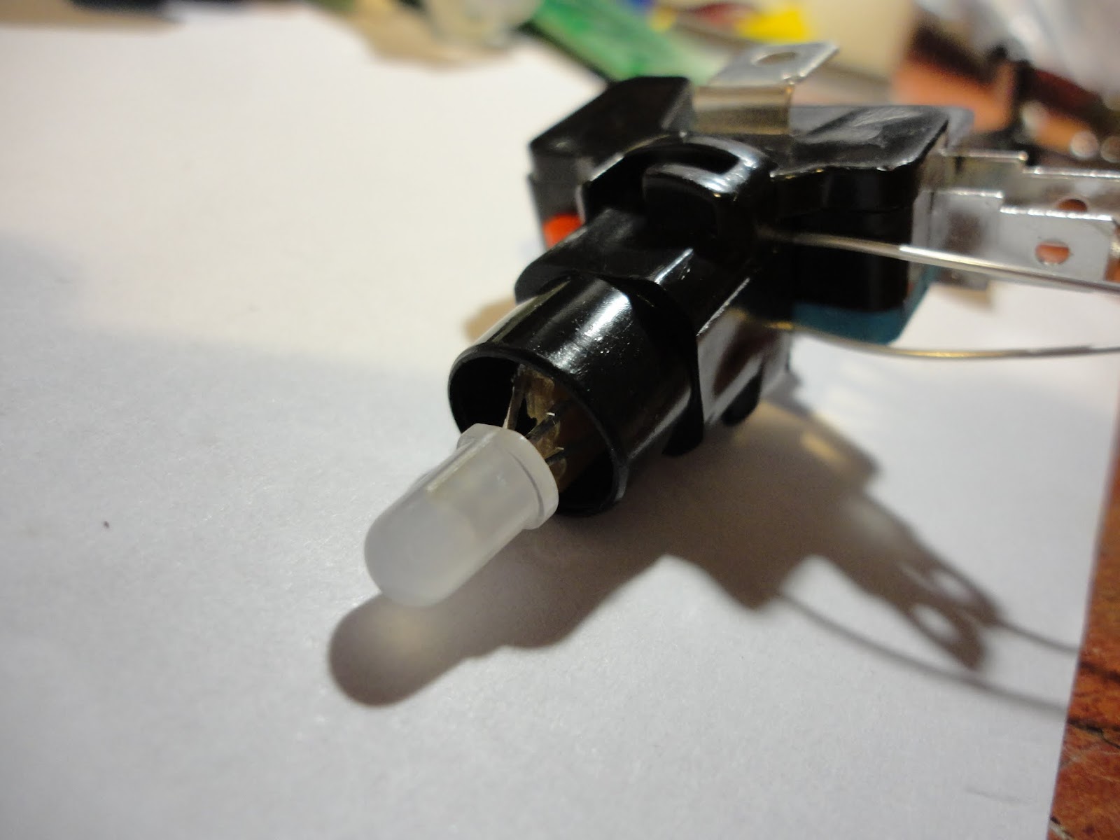
I bought the switches quite a long time before I really decided exactly how I was going to use them. They have translucent white plungers with an LED holder in the microswitch clip at the base. The supplied LEDs were white and resistored up for 12V (I guess as a drop in replacement for filament bulbs in arcade machines). I decided to replace them with RGB LEDs, but I needed to make sure I had a decent scheme for doing this, since I needed to wire up 80 of these switches and didn't want to end up making the same mistake 80 times!
12V LED modules and sockets
Microswitch heaven!
What I ended up with was breaking a matrix board into little squares, so I could thread the leds of the 5mm RGB LED through the holes and slide the board into the socket in place of the white LEDs modules. This worked nicely to connect the common anode and one of the cathodes to the LED socket. I was then faced with somehow getting a connection through to the other two cathodes while not interfering with the operation of the switch.
I have a big roll of Kynar wrapping wire that comes in very handy for this kind of thing. Kynar wire is a single core wire with a very thin insulation layer, so it easily gets through the tiniest of holes and gaps. I could solder two wires to the remaining LED cathodes and thread them down through the socket and out between socket and switch. Since the thin single core wire can be brittle I used little blobs of superglue to anchor the ends after soldering (Its amazing how much more useful superglue becomes if you get a spray can of activator, which sets the glue off instantly - even in blobs)
I am driving my LEDs with LPD6803 chips, which I have a big batch of from an eBay bargain. These are chainable 3-channel, constant current, self-running PWM controllers with a 2 wire serial interface. They allow 5 bits per channel of PWM resolution (Maybe the 8-bit PWM WS2801 would have been better, but I think these LPD6803's are good enough, and they are what I had)
Every single LED needs its own controller chip... thats 80 chips... how to fit them all in? I considered putting an LED driver board on every button but quickly decided that wasn't going actually to make life any easier. In the end I decided to put 8 driver ICs on a PCB and have one PCB per grid column (so 10 boards). There would be a lot of wire in there, but it seemed the most straightforward way to build it.
I've recently started getting small batches of PCBs made up by a supplier in China (ITEAD), and these driver PCBs are only the second batch I have ordered. Just getting the thing wired up to see if it worked (or if I had badly messed up my PCB design) took a long time and the suspense was killing me - but finally I was able to connect up an Arduino to send some data to it... and it worked!!
As well as the 8 x LPD6803 chips the PCB contains a 74HC165 parallel input shift register for reading the switches. I wasn't going to count my chickens until I'd also tested the input part. Wooo, that worked too! (Eventually the input and output driver chips for all the boards will be chained together so the last test will be whether that all works)
The console for the grid is laser-cut 5mm acrylic. I had considered making a box completely out of acrylic, but wondered how sturdy it would be. Eventually I settled on building the box into a flight case and thought cases designed to house 19" rack-mount mixers would be perfect. The one I got is a Reloop case from eBay, where if cost about £75. Not the cheapest way of getting a housing, but it should be good for a few knocks.
So... looks like I have a lot of wiring to do! I am still not certain how I will drive it when its finished, but most likely I will use an Arduino.
I've wanted to make a
“globe POV” for a while after seeing a totally amazing hi-res one
on YouTube a while back. The mechanical side of it (motor drive and
power supply) always put me off a bit – while I think I can design
a PCB and feel pretty confident it's going to work, motors, gears and
bearings are still a matter of kludge and guesswork for me.
I decided to make a 24
LED proof of concept project using the largest size board my free
version of EAGLE would let me work to. I originally intended to use
0805 SMT LEDs mounted on their sides but when I realised what a bitch
they are to solder like that I decided to go with good 'ole 3mm thru
holes of which I have – ahem – about 3,000 blue ones (don't ask).
The electronics was
pretty straightforward – since I have made a few similar things
before (basically this was an Arduino project with a custom designed
PCB) The 24 LEDs are driven by 3 x 74HC595D shift registers through
100 ohm 0805 resistors. I used an Atmega328 in QPF32 package with a
miniature (Nano styley) resonator.
I usually use an FTDI
USB-TTL serial lead for in circuit programming, so I simply added
pads for the the six ICSP connections I needed for burning the
bootloader and temporarily soldered wires to them. In the past I have
routed in a proper 2x3 ICSP header but I don't think I'll bother any
more - after all, burning the bootloader is a one-off procedure and
routing in the header is a pain.
The board is single
sided FR4. After etching and drilling it I tinplated the tracks (I do
this with all my boards now as it makes soldering easier, looks
cooler, doesn't take long, and isn't so expensive). After adding the
wire jumpers to the back I worked in stages to add the components and
test things.
I think its always a
good idea to test at each stage in case you need to junk the board
due to a design problem. First I soldered in the Atmega and the
resonator and burned the bootloader. When that worked I added the
serial programming header, diagnostic LED and resistor and made sure
I could get sketches to run on the Atmega. Only then did I add all
the other components when was confident the brain was alive. I
soldered all the components with an iron, with the exception of the
resonator where I put solder and flux on the pads and used a hot air
tool make the joints.
The rest of it I made
up as I went along, convinced it might go wrong at any moment. I
shaped the board to a disk with a stanley knife, steel rule, pliers
(for snapping) and sandpaper (for smoothing). Then I added in the
slots, top and bottom, to accept a 2mm drive shaft using my new
diamond edge cutting disk on my Proxxon table saw (in retrospect this
blade is fricking awesome and I should have used it to cut out the
circular PCB... you live and learn).
Aligning the 2mm drive
shafts top and bottom was pure guesswork. I both soldered them and
used copious quanitites of cyanoacrylate superglue (with activator
spray) to hold them in place, with the help of a couple of plastic
hub wheels from a model kit supplier.
The drive shafts go
through miniature model bearings in my crudely fashioned frame (made
from MDF I salvaged from an old CD rack, cut with a plain old Bosch
jigsaw) and at the bottom there is a simple reduction gear from a DC
motor to drive it. There is a crude joinery job holding it all
together - I am not proud of it,
What I am more pleased
with was the electrical transfer method I used. In a previous project
I
“borrowed” (saw it on a Youtube video) the idea of using an
axially mounted, graphite-lubricated, 3.5mm jack plug/socket
connection to take power to the rotating LED board while also acting
as a bearing. This time I used some chunky graphite brushes (intended
for drill equipment I think) and drilled a 2.5mm hole in each and
passed the 2mm drive shafts through them, then crudely superglued the
end of the brush springs to my frame. And it worked! In fact it works
rather well and I think I will be using this approach again.
As I expected, some
balancing was needed. I superglued a couple of nuts to the back of
the board to counterbalance the LEDs on the opposite edge. Its not
perfect but it was a big improvement.
I saved soldering the
Hall Sensor until the board was mounted in the frame, so I could make
sure I cut the legs to the right length. A small Neodymium magnet
triggers the sensor.
In hindsight it might
have been better to somehow mount the magnet on the front of the
frame (opposite the vertical part of the frame, so 180 degrees around
the axis from where it is now). The reason is that when the sensor
passes the magnet, a new drawing cycle starts. So this is the point
where the previous draw cycle might be ended early or overrun
(depending on rounding errors due to the timer resolution and
variations in spin speed). With the position of the magnet in my
design these display “glitches” happen right at the front of the
globe and are quite easy to see – it would be better to hide them
around the back by moving the trigger point through 180 degrees, or
by placing the Hall sensor on the same edge as the LEDs rather than
opposite them.
There is a voltage
regulator on the board and I power the motor and board from a common
supply of about 10 volts. Something that surprised me was that when
plugged the USB lead in to the programming header on the board, the
motor received power and span up. I didn't think the current could
cross the regulator in the opposite direction so it was a bit of a
nasty suprise (and presumably it does the regulator no good either).
A 1N4001 rectifier diode on the +10V supply going to the board brush
solved the problem. I was very glad I found this issue before the
motor was attached to the frame or I could have smashed the board.
When it was all fitted
together I tested it out with a simple set of vertical and horizontal
lines, rendering as a wireframe globe, and it looked great. Next I
wanted to display a pixellated map of the world... to get this done I
found a suitable Mercator projection image on Google images and
resized down to the target 24 x 64 pixels in PaintShop Pro (still my
drawing tool of choice for its easy work with small bitmaps). Quite a
bit of manual tweaking was then needed to get a decent recognisable
monochrome image.
The next step was to
calculate the bitmap values to insert in the code. I needed data as 3
bytes for each vertical scan column through the image (64 x 3 bytes
of data) and I needed the low bit positioned at the vertical top of
each byte.
I usually use a
spreadsheet to do this kind of thing (OpenOffice). I wondered how I
might import the mono bitmap image data directly into the
spreadsheet, but as I was in a hurry and the image was small I just
retyped it manually. To help keep track I divided the image into 8x8
squares and highlighted them chessboard fashion in yellow. This meant
I could work one square at a time and it only took 15 minutes or so
to enter the data into the spreadsheet and use formulas to calculate
the bitmap values I needed.
I copy/pasted the
values from the spreadsheet into the Arduino sketch, programmed the
globe and fired it up – and it worked first time! The Pacific
looked a bit empty though, so I went back and added Hawaii.
I put a 32kbit I2C
EEPROM on the board so that I can store a decent set of image data to
make animations possible. I haven't done anything with it yet.
Here is a brief
description of how the code works. Almost all the POV projects I've
made work in this way...
The sketch sets up the
Atmega328's internal timers 1 and 2 to run at the same rate (1/64 of
full clock speed). This means they are counting at a very high rate
(I think it works out as 62500 counts a second).
The sketch uses
“interrupts” – an interrupt is a way for a specific hardware
event (like a pin changing value or an internal timer reaching a
certain threshold) to cause a specific piece of program code (called
a “service routine”) to be run immediately. This means the
program does not need to keep “polling” things like inputs and
timers, which would not be very accurate at these timescales.
Interrupts are really the only way to get the consistent timing
accuracy we need.
We use two interrupts,
one is called when the hall sensor fires and the value on pin 2
(Interrupt 0 pin) changes. The service routine for this interrupt
captures the value of timer 1 and resets the timer. This value is the
number of timer ticks in one complete rotation of the board.
Now we divide this up
to get the number of timer ticks in a single “sector” (vertical
scan column width). Although there are 64 columns in the image, I
actually insert an artificial blank column between every pair of
image columns to cleanly seperate the “pixels” rather than
letting them run together into streaks (it just looks nicer) so I
treat the image like it has 128 columns.
So the timer count is
divided by 128 and the result is put into the timer 2 “period
register”. Now when timer 2 reaches the value of the period
register it is automatically reset and another interrupt fires. The
service routine for this interrupt will therefore get regularly
called 128 times on each revolution – perfect! Now we just need to
load values from the image data into the LEDs. We need to keep a
count of how far round the revolution we are and we can add an
incrementing offset to make the image appear to spin. It is also here
that we turn off all the LEDs on every other call to add the gaps
between the pixels.
The LEDs are loaded by
simple shift register stuff (Check the Arduino tutorials if you don't
know what a shift register is) . Speed is of the essence, so the
three shift registers are loaded in parallel using 3 data lines and
common clock lines. I avoid using digitalWrite() to drive the output
pins on anything like this and go direct to the port registers since
it's an order of magnitude faster!