Still an ongoing project to play Atari Battlezone via a laser projector (for no other reason than I like a challenge :)).
I stumbled for a long time over pushing data fast enough to a microcontroller, with a USB serial port proving too slow and a USB isosynchronous device being very complicated to program. Now I am using an mbed microcontroller board (with a decent amount of RAM and fast clock) to receive data and drive the DACs, and with the ethernet support of the mbed, I am able to send data over a TCP socket, which seems to be plenty fast enough.
The mbed's speed and RAM also allowed me to do a lot of the number crunching on the microcontroller (in particular the plotting of lines) so all I need is to push the lists of vertices to the mbed and it will generate "in between" points along a line (required so that the laser galvos can be moved a bit more incrementally - and with less probems of intertia -than just throwing them at the raw vertices. Also means I can keep plotting a frame while the next one arrives.
The "hard bit" - the actual Battlezone game - is actually easy, since I am using the wonderful open-source MAME emulator and was simply able to locate the vector display emulation code and hook my stuff into it. Luckily Battlezone does output vectors with decent continuity (i.e. where lines join up they tend to be sent consecutively, which saved me sorting list into some kind of optimised plot order). So basically my hooks in the MAME vector code just convert the floating point vector coordinates into 12 bit integer values (for my ADC) and flag "move" vs "draw" actions. Then the list can be dumped to the TCP socket at the end of the refresh cycle. At the moment I am only outputting every 10th frame to let the microcontroller breathe.
On the mbed side I am using a MCP4922 12-bit dual Digital to Analog Converter (DAC) with SPI serial interface, which can easily be driven from the mbed. The DACs drive a 20kpps Galvo set purchased from ebay (about £100 including PSU and drivers). I also have a 6N139 opto isolator driving the TTL blanking for the laser (a 50mW green DPSS module from Aixiz).
I am still working on the mbed code... at the moment I use a kind of double buffering with 2x16kb buffers, one of which can receive the frame buffer from TCP/IP socket while the mbed is plotting the other. Between plots the mbed checks if the receive frame is complete and switches the buffers if this is the case.
The frame rate I can plot is too slow, and I need to work out how to make it better. I need to force delays during plotting to allow the mechanical galvos to catch up with the driver signal. These are all <1ms but they add up and reduce the frame rate. Also the lines are "plotted" with "in-between" point calculation to try to keep galvo movement rate reasonable. I need to work out the best combination of delays and divisions to get the best plot with the best framerate. I am also thinking about recognising the text at the top of the display (status text and scanner) and missing them out of the plot (text kills the plot rate)
Still a work in progress, but fun!
Sunday, 19 December 2010


Saturday, 27 November 2010
Tesla coil diary - part 2

I've been playing on and off with the coil for the last couple of months, but the first test a few weeks ago was a little bit disappointing, only managing sparks of 6" or so and then only to ground (no air streamer breakout event with a breakout point on the top)
At first I thought the problem was positioning of the primary coil tap (i.e. change the number of active turns on the bottom coil) but I still could not get any better than 6" sparks to ground. Then I started to play with the spark gap and found that using a spacer to force a larger gap between the lengths of copper tube making up my static gap, the sparks improved a bit. That is until the spacers caught fire :)
So, I decided to try with a simple rotary spark gap and holy crap did it make a difference! Here it is...

I used 5mm acrylic sheet as a base material and a nominal 3000rpm shaded pole motor running at 240VAC. In theory 3000rpm is 50 revs per second. With the spark gap opening twice per rev (i.e. presenting at zero and 180 degrees) this should give 100 breaks a second I think... in theory this is perfect for discharging the capacitor bank just as it reaches maximum charge twice (positive and negative) on each mains AC 50Hz cycle.
Thats the theory, but its not a proper synchronous motor and the load of the spinning gaps looks likely slow it down a bit... if I get on to tuning things further I might try to work out its actual RPM. The motor is fitted to a base plate which can be rotated so the phase (i.e. when in mains cycle the breaks happen) can be changed, but I think this is really only going to be of value if the break rate really is 100Hz. I haven't played with moving the motor yet, something for another day.
Well... here are the results, without any serious attempt at tuning the primary tap.
Some other recent additions are a Terry Filter (safety spark gap and surge filter which protects the Neon Sign Transformer getting fried)


When I was packing it all up I was rather perturbed to receive small electric shocks every time I touched the secondary connections. At first I thought I had done something dumb like leave the mains connected or that the primary capacitors had remained charged somehow. However I got shocks handling the secondary even after I had completely removed it from the rest of the setup and I think the PVC pipe and/or the varnish layer were storing a static charge which leaked slowly over to the copper wire. The outside of the varnish certainly had a static charge like a TV screen right after the coil had been run. Interesting!
Sunday, 24 October 2010
Solenoid Drum Machine
Just a quick project to try out some new push solenoids...
Based on PIC16F688 and building on the MIDI input code used on my earlier POKEY project

include <system.h>
#include <memory.h>
#pragma DATA _CONFIG, _MCLRE_OFF & _WDT_OFF & _INTRC_OSC_NOCLKOUT
#pragma CLOCK_FREQ 8000000
typedef unsigned char byte;
// define the pins
//#define P_LED portc.0
// MIDI defs
#define MIDIMSG(b) ((b)>>4)
#define MIDICHAN(b) ((b)&0xf)
#define MIDIMSG_NOTEON 0x09
#define MIDIMSG_NOTEOFF 0x08
// MIDI message registers
byte runningStatus = 0;
int numParams = 0;
byte midiParams[2] = {0};
#define SZ_RXBUFFER 20
byte rxBuffer[SZ_RXBUFFER];
byte rxHead = 0;
byte rxTail = 0;
int tmr[4] = {0};
////////////////////////////////////////////////////////////
// INTERRUPT HANDLER CALLED WHEN CHARACTER RECEIVED AT
// SERIAL PORT
void interrupt( void )
{
// check if this is serial rx interrupt
if(pir1.5)
{
// get the byte
byte b = rcreg;
// calculate next buffer head
byte nextHead = (rxHead + 1);
if(nextHead >= SZ_RXBUFFER)
{
nextHead -= SZ_RXBUFFER;
}
// if buffer is not full
if(nextHead != rxTail)
{
// store the byte
rxBuffer[rxHead] = b;
rxHead = nextHead;
}
}
}
////////////////////////////////////////////////////////////
// INITIALISE SERIAL PORT FOR MIDI
void init_usart()
{
pir1.1 = 1; //TXIF
pir1.5 = 0; //RCIF
pie1.1 = 0; //TXIE no interrupts
pie1.5 = 1; //RCIE interrupt on receive
baudctl.4 = 0; // SCKP synchronous bit polarity
baudctl.3 = 1; // BRG16 enable 16 bit brg
baudctl.1 = 0; // WUE wake up enable off
baudctl.0 = 0; // ABDEN auto baud detect
txsta.6 = 0; // TX9 8 bit transmission
txsta.5 = 1; // TXEN transmit enable
txsta.4 = 0; // SYNC async mode
txsta.3 = 0; // SEDNB break character
txsta.2 = 0; // BRGH high baudrate
txsta.0 = 0; // TX9D bit 9
rcsta.7 = 1; // SPEN serial port enable
rcsta.6 = 0; // RX9 8 bit operation
rcsta.5 = 1; // SREN enable receiver
rcsta.4 = 1; // CREN continuous receive enable
spbrgh = 0; // brg high byte
spbrg = 15; // brg low byte (31250)
}
byte rxInc(byte *pbIndex)
{
// any data in the buffer?
if((*pbIndex) == rxHead)
return 0;
// move to next char
if(++(*pbIndex) >= SZ_RXBUFFER)
(*pbIndex) -= SZ_RXBUFFER;
return 1;
}
////////////////////////////////////////////////////////////
// RECEIVE MIDI MESSAGE
// Return the status byte or 0 if nothing complete received
// caller must check midiParams array for byte 1 and 2
byte receiveMessage()
{
// buffer overrun error?
if(rcsta.1)
{
rcsta.4 = 0;
rcsta.4 = 1;
}
// any data in the buffer?
if(rxHead == rxTail)
return 0;
// peek at next char in buffer
byte rxPos = rxTail;
byte q = rxBuffer[rxPos];
// is it a channel msg
if((q&0x80)>0)
{
runningStatus = 0;
switch(q&0xf0)
{
case 0x80: // Note-off 2 key velocity
case 0x90: // Note-on 2 key veolcity
case 0xA0: // Aftertouch 2 key touch
case 0xB0: // Continuous controller 2 controller # controller value
case 0xC0: // Patch change 2 instrument #
case 0xE0: // Pitch bend 2 lsb (7 bits) msb (7 bits)
runningStatus = q;
numParams = 2;
break;
case 0xD0: // Channel Pressure 1 pressure
runningStatus = q;
numParams = 1;
break;
case 0xF0: // (non-musical commands) - ignore all data for now
return q;
}
// step over the message
if(!rxInc(&rxPos))
return 0;
}
// do we have an active channel message
if(runningStatus)
{
// read params
for(int thisParam = 0; thisParam < numParams; ++thisParam)
{
midiParams[thisParam] = rxBuffer[rxPos];
if(!rxInc(&rxPos))
return 0;
}
// commit removal of message
rxTail = rxPos;
return runningStatus;
}
else
{
// remove char from the buffer
rxInc(&rxTail);
return q;
}
return 0;
}
void main()
{
// osc control / 8MHz / internal
osccon = 0b01110001;
// timer0... configure source and prescaler
cmcon0 = 7;
// enable serial receive interrupt
intcon = 0b11000000;
pie1.5 = 1;
// configure io
trisa = 0b00010000;
trisc = 0b00110000;
ansel = 0b00000000;
porta=0;
portc=0;
memset(tmr,0,sizeof(tmr));
// initialise MIDI comms
init_usart();
// loop forever
for(;;)
{
// get next MIDI note
byte msg = receiveMessage();
if(msg)
{
byte note = midiParams[0];
if(note >= 48 && note < 52)
{
int which = note-48;
// 0x90 note on
// 0x80 note ff
if((msg & 0xf0) == 0x90)
{
tmr[which] = 200;
}
}
}
for(int i=0;i<4;++i)
{
if(tmr[i] > 0)
tmr[i]--;
}
porta.2 = (tmr[0]>0)?1:0;
portc.0 = (tmr[1]>0)?1:0;
portc.1 = (tmr[2]>0)?1:0;
portc.2 = (tmr[3]>0)?1:0;
}
}
Based on PIC16F688 and building on the MIDI input code used on my earlier POKEY project

include <system.h>
#include <memory.h>
#pragma DATA _CONFIG, _MCLRE_OFF & _WDT_OFF & _INTRC_OSC_NOCLKOUT
#pragma CLOCK_FREQ 8000000
typedef unsigned char byte;
// define the pins
//#define P_LED portc.0
// MIDI defs
#define MIDIMSG(b) ((b)>>4)
#define MIDICHAN(b) ((b)&0xf)
#define MIDIMSG_NOTEON 0x09
#define MIDIMSG_NOTEOFF 0x08
// MIDI message registers
byte runningStatus = 0;
int numParams = 0;
byte midiParams[2] = {0};
#define SZ_RXBUFFER 20
byte rxBuffer[SZ_RXBUFFER];
byte rxHead = 0;
byte rxTail = 0;
int tmr[4] = {0};
////////////////////////////////////////////////////////////
// INTERRUPT HANDLER CALLED WHEN CHARACTER RECEIVED AT
// SERIAL PORT
void interrupt( void )
{
// check if this is serial rx interrupt
if(pir1.5)
{
// get the byte
byte b = rcreg;
// calculate next buffer head
byte nextHead = (rxHead + 1);
if(nextHead >= SZ_RXBUFFER)
{
nextHead -= SZ_RXBUFFER;
}
// if buffer is not full
if(nextHead != rxTail)
{
// store the byte
rxBuffer[rxHead] = b;
rxHead = nextHead;
}
}
}
////////////////////////////////////////////////////////////
// INITIALISE SERIAL PORT FOR MIDI
void init_usart()
{
pir1.1 = 1; //TXIF
pir1.5 = 0; //RCIF
pie1.1 = 0; //TXIE no interrupts
pie1.5 = 1; //RCIE interrupt on receive
baudctl.4 = 0; // SCKP synchronous bit polarity
baudctl.3 = 1; // BRG16 enable 16 bit brg
baudctl.1 = 0; // WUE wake up enable off
baudctl.0 = 0; // ABDEN auto baud detect
txsta.6 = 0; // TX9 8 bit transmission
txsta.5 = 1; // TXEN transmit enable
txsta.4 = 0; // SYNC async mode
txsta.3 = 0; // SEDNB break character
txsta.2 = 0; // BRGH high baudrate
txsta.0 = 0; // TX9D bit 9
rcsta.7 = 1; // SPEN serial port enable
rcsta.6 = 0; // RX9 8 bit operation
rcsta.5 = 1; // SREN enable receiver
rcsta.4 = 1; // CREN continuous receive enable
spbrgh = 0; // brg high byte
spbrg = 15; // brg low byte (31250)
}
byte rxInc(byte *pbIndex)
{
// any data in the buffer?
if((*pbIndex) == rxHead)
return 0;
// move to next char
if(++(*pbIndex) >= SZ_RXBUFFER)
(*pbIndex) -= SZ_RXBUFFER;
return 1;
}
////////////////////////////////////////////////////////////
// RECEIVE MIDI MESSAGE
// Return the status byte or 0 if nothing complete received
// caller must check midiParams array for byte 1 and 2
byte receiveMessage()
{
// buffer overrun error?
if(rcsta.1)
{
rcsta.4 = 0;
rcsta.4 = 1;
}
// any data in the buffer?
if(rxHead == rxTail)
return 0;
// peek at next char in buffer
byte rxPos = rxTail;
byte q = rxBuffer[rxPos];
// is it a channel msg
if((q&0x80)>0)
{
runningStatus = 0;
switch(q&0xf0)
{
case 0x80: // Note-off 2 key velocity
case 0x90: // Note-on 2 key veolcity
case 0xA0: // Aftertouch 2 key touch
case 0xB0: // Continuous controller 2 controller # controller value
case 0xC0: // Patch change 2 instrument #
case 0xE0: // Pitch bend 2 lsb (7 bits) msb (7 bits)
runningStatus = q;
numParams = 2;
break;
case 0xD0: // Channel Pressure 1 pressure
runningStatus = q;
numParams = 1;
break;
case 0xF0: // (non-musical commands) - ignore all data for now
return q;
}
// step over the message
if(!rxInc(&rxPos))
return 0;
}
// do we have an active channel message
if(runningStatus)
{
// read params
for(int thisParam = 0; thisParam < numParams; ++thisParam)
{
midiParams[thisParam] = rxBuffer[rxPos];
if(!rxInc(&rxPos))
return 0;
}
// commit removal of message
rxTail = rxPos;
return runningStatus;
}
else
{
// remove char from the buffer
rxInc(&rxTail);
return q;
}
return 0;
}
void main()
{
// osc control / 8MHz / internal
osccon = 0b01110001;
// timer0... configure source and prescaler
cmcon0 = 7;
// enable serial receive interrupt
intcon = 0b11000000;
pie1.5 = 1;
// configure io
trisa = 0b00010000;
trisc = 0b00110000;
ansel = 0b00000000;
porta=0;
portc=0;
memset(tmr,0,sizeof(tmr));
// initialise MIDI comms
init_usart();
// loop forever
for(;;)
{
// get next MIDI note
byte msg = receiveMessage();
if(msg)
{
byte note = midiParams[0];
if(note >= 48 && note < 52)
{
int which = note-48;
// 0x90 note on
// 0x80 note ff
if((msg & 0xf0) == 0x90)
{
tmr[which] = 200;
}
}
}
for(int i=0;i<4;++i)
{
if(tmr[i] > 0)
tmr[i]--;
}
porta.2 = (tmr[0]>0)?1:0;
portc.0 = (tmr[1]>0)?1:0;
portc.1 = (tmr[2]>0)?1:0;
portc.2 = (tmr[3]>0)?1:0;
}
}
Saturday, 18 September 2010
Tesla Coil Diary - Part 1
I've wanted to own a Tesla coil pretty much since I knew what one was, but I always thought it would be a bit difficult to make and possibly a little bit dangerous... Anyway, I decided to bite the bullet and started gathering the bits a couple of months back and actually started the building of it a couple of weeks ago after I got the courage to fire up the 10kV Neon Sign Transformer I got off ebay.
I got all the information and many great tips of websites of other coilers and have borrowed many ideas. I will try to remember and credit as much as I can.
I started off by getting this neon transformer
 its a 10kV 50mA F.A.R.T. (oh the fun!) Resinblock. Here is my first try out of it, making a Jacobs ladder from coat hanger wire....
So far so good...
After a bit of online reading I eventually decided to wind my secondary coil on 125mm PVC ducting pipe (After deciding the 68mm drainpipe I first bought was just too wimpy). I got a nice 2Kg reel of 0.71mm magnet wire from ebay and got winding. I initially rigged up a motor driven jig to wind the wire but ended up winding by hand so I could keep a good tension on the wire (The motor came in very useful later while varnishing). I wound 800 turns in a couple of hours then put on about 5 coats of polyurethane gloss varnish. I used kapton tape to secure the outer windings (I owe http://deepfriedneon.com/ for many tips I used ... given my DIY prowess, without this information I would have ended in disaster I am sure)
Here is my winding rig...




I got all the information and many great tips of websites of other coilers and have borrowed many ideas. I will try to remember and credit as much as I can.
I started off by getting this neon transformer

So far so good...
After a bit of online reading I eventually decided to wind my secondary coil on 125mm PVC ducting pipe (After deciding the 68mm drainpipe I first bought was just too wimpy). I got a nice 2Kg reel of 0.71mm magnet wire from ebay and got winding. I initially rigged up a motor driven jig to wind the wire but ended up winding by hand so I could keep a good tension on the wire (The motor came in very useful later while varnishing). I wound 800 turns in a couple of hours then put on about 5 coats of polyurethane gloss varnish. I used kapton tape to secure the outer windings (I owe http://deepfriedneon.com/ for many tips I used ... given my DIY prowess, without this information I would have ended in disaster I am sure)
Here is my winding rig...

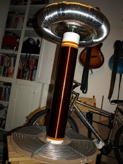
I was quite pleased with the end result, which looked nicely like something from a B-movie mad scientists lab.
I originally bought 6mm microbore copper tubing to make my primary coil, but realised that I had not bought enough, and it was rather too expensive to go and buy another, longer length, so I looked around for alternatives and found some 4.75mm solid aluminium wire at the much better price of £12 for 20 metres. The wire was a lot softer and easier to kink than I expected and at first I wasn't too happy with the result. But after some reworking I think its OK. Here is the result (set on MDF with acrylic stands secured with nylon zipties)

I managed about 17 turns. I think I need to tap the coil after about 10 turns based on what Tesla Coil CAD told me - but I thought it would be good to have the extra tunability offered by the extra coils
For the top load I got some 10mm semi-rigid aluminium ducting hose (as is a coiler traditional I believe) and set it between two 34cm steel trays from the local 99p shop (these have to be the best bargain of this build!). This whole procedure was more difficult than it probably sounds... I needed to bolt the trays together first, with a wood spacer, then use tensioned strips of gaffer tape to hold the 2 plates parallel to each other. Then I threaded a rubber bungee cord through the flexible duct and after putting the ducting around the rim of the trays I hooked up the bungee and spread the out ducting round the rim until it joined up. I used a bit of flexible plastic sheet to make a sleeve to put inside one end of the ducting and help join the ends together. A bit of aluminium tape joined the ends, then more aluminimum tape to secure the ducting on the rim of the trays (helpful tips from http://www.hvtesla.com/toroid.html)


It might not be the best looking toroid, but it does look pretty meaty and mean!
Next steps are to add a strike rail to the primary (finally getting some use out of that microbore copper pipe), build a chassis (in progress - out of chipboard and softwood) and add fittings to secure it all together properly without danger of it collapsing. In the mean time here are the parts stacked on top of each other for a photo opportunity....


And so onto the electrics... I threw caution to the wind and got some Cornell Dubilier 942C20P15K-F capacitors, which a bit of online research seemed to indicate were THE choice for a good coil, even though they are not cheap, especially when factoring postage from US to UK. My capacitor bank has 28 of these 0.15uF, 2000V capacitors arranged in two parallel strings of 14. I mounted them on clear acrylic and wired them up with 1M bleeder resistors using high current wire taken from a set of car jump leads.

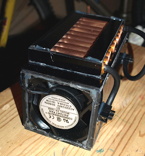
I just made my spark gap this weekend... I initially intended making a cylindrical "Richard Quick" type design but I preferred the idea I saw on a web site (which I would credit if I could find it again) where the multiple copper tubes are laid out side by side on the top of a box, and air is drawn through them by fans mounted on the ends of the box. Airflow keeps the gaps cool, but also sucks away ionised air from the gaps and quenches the sparks more quickly, which (so I read) results in better operation of the coil.
I made the spark gap box from acrylic sheets with an 85mm 240VAC fans (from Maplin) mounted at each end. 10 copper tubes of 15mm diameter and 90mm length form the gap. Two layers of kapton tape at each end of each copper tube provide spacing of ~0.4mm between tubes when they are laid side by side. Connection is made (at the moment) by a plug of compressed aluminium foil around which is wound the connection wire (car jump lead) inside the two "terminal" tubes. I am not sure how well this arrangment is going to work... we shall see.. The tubes are not permanently attached to the box, so my idea is that the number of tubes included in the gap can be varied by moving one of the tubes to which the wire is attached (the other being fixed at one side) by simply removing and shuffling the tubes.


I still need to complete build of the Terry Filter circuit (which I hope will protect the neon transformer from voltage surges) as well as the structural bits and pieces, however I hope I can get this thing up and running before too much longer. Watch this space for the results....
Wednesday, 30 June 2010
DIY Boss PC-2 / Amdek PCK100 Analog Percussion Synth
Back at the end of the 80's I went in a music shop in London and on impulse I bought this wierd BOSS box that made weird bloopy noises... a PC-2 Percussion Synthesizer. It wasn't a difficult decision at the time since it only cost me £10 brand new boxed (I think they were trying to get rid of them) and it came with a free brand new BOSS HC-2 Hand Clapper pedal, although that seemed even less useful (though the guy did a good sales pitch involving a tale about a friend with no arms who had trouble applauding at gigs... :o)


Apart from a bit of novelty value I gotta be honest they didn't get a lot of use... I think the HC-2 got chucked during a house cleanout and the PC-2 was sold on ebay a few years back (and was amazed to get £100 for it). Well now I am kicking myself and wished I'd held on to these two collectables.
So when I saw the schematic of the Amdek PCK100 online (actually a kit form of the PC-2 sold by a Roland affiliate) I decided to try to make one and once again re-live boingy noise heaven.
On the page http://www.effectsdatabase.com/model/amdek/pck100 where I found the schematic I also found a photo of the PCB and decided to try to use it directly. With some manipulation in Paint Shop Pro and the use of Press'n'Peel PCB etching film I was able to make a copy of the board and after working out some workarounds (e.g. using BA6110 instead of ultra-rare BA662A VCA chip) I actually got it to work.. So in case you're interested ..here is how I did it
1) I started off with this photo of the track side of the original PCB
 2) Turned to mono, upped the contrast, then very carefully use the "eraser" tool to ensure there are good clean gaps between all the tracks
 3) Marked drill holes with circles
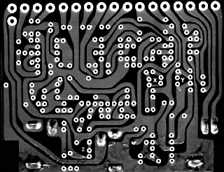 4) Drop colour depth to 2 colours
 5) Negative image and a few embellishments and its ready to press'n'peel
 6) Laser printed etch-resist transferred to copper clad board using a hot iron
 7) Etched, drilled and trimmed ready for components
 I mounted the board inside a project box from Maplin. By the way I have a thing for Dymo embossed label tape :)


The Amdek user guide gives info on some mods to the board (VCO wave form change, mod waveform change) which I added toggle switches for. Usually the Sweep control is a center tap pot.. I didn't have one so I instead rigged up a DPDT toggle and a resistor to a normal pot so that the same effect could be acheived (although I am not sure it works so well)
The original board calls for a Roland BA662A VCA chip... you won't find one! you can use a similar BA6110 chip but the pinout is different. I found the following worked


Apart from a bit of novelty value I gotta be honest they didn't get a lot of use... I think the HC-2 got chucked during a house cleanout and the PC-2 was sold on ebay a few years back (and was amazed to get £100 for it). Well now I am kicking myself and wished I'd held on to these two collectables.
So when I saw the schematic of the Amdek PCK100 online (actually a kit form of the PC-2 sold by a Roland affiliate) I decided to try to make one and once again re-live boingy noise heaven.
On the page http://www.effectsdatabase.com/model/amdek/pck100 where I found the schematic I also found a photo of the PCB and decided to try to use it directly. With some manipulation in Paint Shop Pro and the use of Press'n'Peel PCB etching film I was able to make a copy of the board and after working out some workarounds (e.g. using BA6110 instead of ultra-rare BA662A VCA chip) I actually got it to work.. So in case you're interested ..here is how I did it
1) I started off with this photo of the track side of the original PCB


The Amdek user guide gives info on some mods to the board (VCO wave form change, mod waveform change) which I added toggle switches for. Usually the Sweep control is a center tap pot.. I didn't have one so I instead rigged up a DPDT toggle and a resistor to a normal pot so that the same effect could be acheived (although I am not sure it works so well)
The original board calls for a Roland BA662A VCA chip... you won't find one! you can use a similar BA6110 chip but the pinout is different. I found the following worked
- socket 1 connect to BA6110 pin# 4
- socket 2 connect to BA6110 pin# 2
- socket 3 connect to BA6110 pin# 1
- socket 4 no connection. BA6110 pin#3 connected to GND (pin 5)
- socket 5 connect to BA6110 pin#5
- socket 6 connect to BA6110 pin#6
- socket 7 connect to BA6110 pin#7
- socket 8 connect to BA6110 pin#8
- socket 9 connect to BA6110 pin#9

Tuesday, 11 May 2010
Battlezone with lasers
This is a project I've had simmering on the back burner for a while. Still at the early stages but thought it might be fun to keep track of each step here
A few months back I got a 20kps laser scanner galvo set off ebay with the intention of making my own laser projector and a vision of using it to play some old vector arcade games... particularly my old fave Atari Battlezone. The arcade game bit seemed pretty easy, since you can play BZ on the open source MAME emulator so I thought I could hook into the vector terminal emulation.
I found the asynchronous UART on an Arduino board was not quite fast enough to cope with the data... dropping bits all over the place, so I started looking at a USB conneciton to a PIC2455. As a SourceBoost C user I was not able to find any easy to understand USB CDC (Communication Device Class, a.k.a serial port) implementations for the PIC - so I decided to make my own, leaning heavily on sample code I found online.
Well I finally got to the point where my PIC would connect via USB show up as a COM port and be easy to access from a Windows program. Then I hooked up an 12-bit SPI dual DAC and connected it to the galvo setup and tried the first random hacking into MAMEs vector module.
I didn't expect it to work first time, and didn't! but my impatient hacking did produce some interesting squiggles at about 2 fps. I needed to use a long exposure photograph to actually make sense of it, but eventually I recognised a couple of parts of the display and got quite excited that the concept was proved!
The coordinate handling is obviously messed up and the image is wrapping on itself multiple times, also there is no attempt at blanking yet - so there are stray lines all over. The big job will be to find some way to optimise the render list to stop throwing the galvos all over the place and improve on the 2 fps refresh!
As you can see I have a long way to go!
Here is the plot showing the bits I recognised


A few months back I got a 20kps laser scanner galvo set off ebay with the intention of making my own laser projector and a vision of using it to play some old vector arcade games... particularly my old fave Atari Battlezone. The arcade game bit seemed pretty easy, since you can play BZ on the open source MAME emulator so I thought I could hook into the vector terminal emulation.
I found the asynchronous UART on an Arduino board was not quite fast enough to cope with the data... dropping bits all over the place, so I started looking at a USB conneciton to a PIC2455. As a SourceBoost C user I was not able to find any easy to understand USB CDC (Communication Device Class, a.k.a serial port) implementations for the PIC - so I decided to make my own, leaning heavily on sample code I found online.
Well I finally got to the point where my PIC would connect via USB show up as a COM port and be easy to access from a Windows program. Then I hooked up an 12-bit SPI dual DAC and connected it to the galvo setup and tried the first random hacking into MAMEs vector module.
I didn't expect it to work first time, and didn't! but my impatient hacking did produce some interesting squiggles at about 2 fps. I needed to use a long exposure photograph to actually make sense of it, but eventually I recognised a couple of parts of the display and got quite excited that the concept was proved!
The coordinate handling is obviously messed up and the image is wrapping on itself multiple times, also there is no attempt at blanking yet - so there are stray lines all over. The big job will be to find some way to optimise the render list to stop throwing the galvos all over the place and improve on the 2 fps refresh!
As you can see I have a long way to go!
Here is the plot showing the bits I recognised

Here is an actual MAME screen showing what it should look like

If things improve I will post an update!
Monday, 3 May 2010
Motion detection to midi with puredata
another experiment with puredata, webcam image is passed through pix_movement object and a pix_blob turns the result into two midi note streams which are sent into reason via midi yoke. the image is the output of the pix_movement (difference between frames)
I put the pd patch at http://sites.google.com/site/skriyl/Home/pd-projects (motion noise.pd)

The patch outputs on midi channels 1 and 2. I used midi yoke and PD's midi output, then piped this into propellerheads reason, where you can use the "advanced midi" to set up midi bus A then lock down channels 1 and 2 to specific instruments in the rack. I used an NNXT with glockenspiel patch and nn19 with strings patch
I put the pd patch at http://sites.google.com/site/skriyl/Home/pd-projects (motion noise.pd)

The patch outputs on midi channels 1 and 2. I used midi yoke and PD's midi output, then piped this into propellerheads reason, where you can use the "advanced midi" to set up midi bus A then lock down channels 1 and 2 to specific instruments in the rack. I used an NNXT with glockenspiel patch and nn19 with strings patch
Subscribe to:
Posts (Atom)
