I was asked to make an installation for the Sound Plotting sound-art festival at Brighton's Stanmer Park in August 2022. I had some small solar panels (Seeed Studio 0.5W solar panel) knocking about from another project and I decided to put those to use.
I knew that these panels are very sensitive to changes in the amount of light falling on them and so I hit on the idea of making a mobile with the panel at one end of each arm, and an oscillator at the other. The idea being that the oscillator pitch would change as the mobile blew around and the angle of sunlight changed.
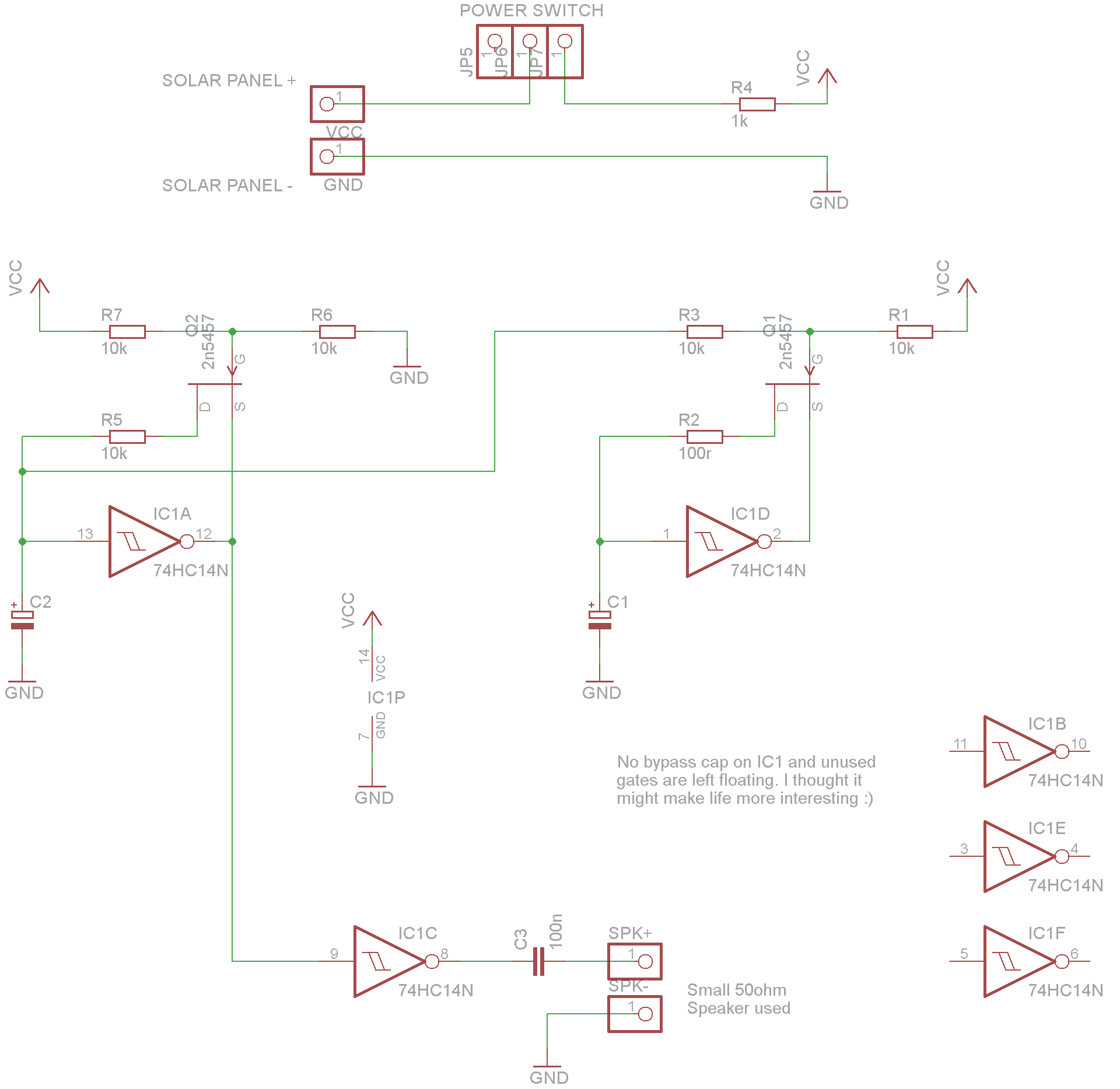
My first experiements with simple Schmitt Trigger Inverter (74HC14) oscillators had mixed results; it seemed like the volume changed more than the pitch.
I experimented with putting a JFET transistor in the feedback connection of the oscillator and found this gave a much more satisfying sweep of pitch as the power supply voltage changed. The gate of the JFET was simply held at half the power supply voltage using a divider made of two 10k resistors.
Even better I found that, rather than tying the low side of that divider to ground, I could use the voltage from the high side of the timing capacitor of another oscillator and get some pitch modulation. Using a large capacitor value (slower frequency) on the modulating oscillator and smaller capacitor value on the modulated oscillator (audio frequency) gave some satisfying whining.
The output from the higher frequency oscillator is buffered through a spare gate and fed to a speaked via a 100nF capacitor. I had some small speakers spare which had an (unusual?) 50ohm impedence, which worked well enough without any further amplification. The result is fairly quiet but just enough to give ambient chirps and tweets without being too intrusive.
My mobile has four levels and I chose different capacitor values for each, so they have different sounds from each other, with 2.2uF and 4.7uF used on the audio oscillator side (C1) and 100nF, 470nF used on the low frequency oscillator sid (C2)
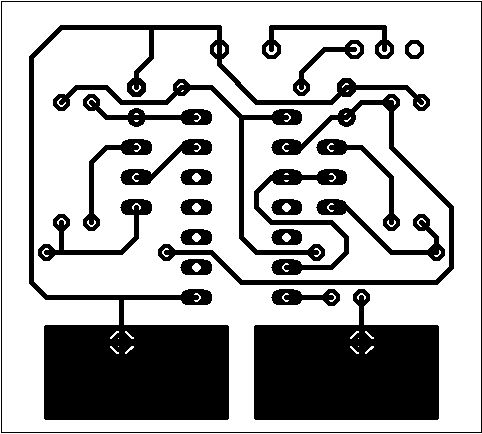
I used enamalled copper wire to link the solar panel to the home-etched boards, and soldered the board directly to the speaker terminals.
With a decent breeze and some sunshine it sounds like sad birds, crying kittens, dying angels (make your own mind up)
A while back I converted an old Vectrex vector CRT games console so that the display could be controlled directly by voltage signals from a modular synth (after being inspired by a demo I saw from Andrew Duff)
Since then I have occasionally thoughts about making synth modules that might work well with the setup and one idea was something to enable isometric "3D" surface plotting from the synth. Back in my school days I messed around with making little isometric 3D demo programs on the BBC Micro computers at school and remembered it being pretty easy to do.. Basically if you have "logical" x and y position and a z position which is some function of x and y, then you can plot on the screen as basically
Xscreen = (x - y)
Yscreen = (x + y + z)
with appropriate scaling and offsetting to place (0,0) at the bottom centre of the screen. The line x=y then runs vertically up the middle of the screen.
My idea was that I'd use a ramp waveform from an oscillator (VCO) on my modular synth to scan the "logical" x axis at high frequency. Every time the scan completed I'd increment a position along the y axis until we'd traced a series of (say) 16 horizontal lines.
To generate the screen X and Y (which can be fed to the Vectrex as analog voltages) we can use voltage summing to evaluate the equations above (subtraction would mean inverting a voltage before adding it)
Once we've done that we can add a z component from another oscillator etc, which is then added to the Y voltage, and with appropriate scaling and offsetting we should get a "3D" plot of the z component on an isometric grid.. in theory!
Ideally we'd have a z that is a function of x and y so that the plot remains "fixed" on the grid. To start with I intended trying to get the same effect by messing by trial and error fine-tuning and messing with oscillator hard syncing.
So the first challenge was to generate the logical y coordinate from the VCO ramp voltage (x). What we want is a "stepped" voltage ramp with 16 equally spaced steps, where we move to the next step (y) only when the VCO ramp resets back to zero at the end of its cycle. Each full y-ramp should take exactly 16 x-ramps to complete.
I did this with a counter chip (CD4040) which fed into an R-2R resistor ladder (forming a digital to analog converter). Using one gate of a CD40106 hex inverter schmitt-trigger i could convert the VCO ramp into a pulse wave with a falling edge at the end of the cycle. This pulse clocked the counter and the lower 4 output bits of the counter fed the DAC (the upper 8 bits can just be left unconnected and ignored).
I had an integrated R-2R resistor network (4610X-R2R-103LF) component handy and used the 4 most significant bits (I tied lower bits to ground) but it would have been pretty easy to make an R-2R network from discrete resistors.
The R-2R DAC output is buffered by an LM358. I also buffered the VCO input using the other opamp gate. Note that the LM358 is not rail to rail so I ran it at 12V and ran the IC's through a 9V voltage reg so there was plenty of headroom.
This is what it looked like on breadboard...
It seemed to get the desired result!
I also thought it would be useful to have a "start of plot" signal output from the circuit for hard syncing a VCO at the start of the grid plot. For this I just hooked up bit 3 of the counter output to another gate on the 40106 (so I'd get a buffered rising edge when the bit 3 of the counter rolls round to zero). I also buffered the counter clock via the 40106 as I thought that might also be useful for hard synching an oscillator.
Then I got to work playing..
I used the ramp out of a Befaco Even VCO module to drive the logical x axis.
A Befaco dual A*B+C module did the x-y and x+y voltage adding
A second Befaco dual A*B+C module did the z-scaling/adding to x+y voltage and also x-y offsetting
The X and Y voltages went via an mcop 4x4 matrix mixer where they could also be attenuated, sent to the Vectrex X and Y connections and to audio (although none of this sounded so good!) plus a component of these voltages could be sent to the Vectrex brightness channel so brightness patterns could also be "plotted" on the grid
I tried various sources for the z-voltage, from simple sine waves with and without hard-sync, FM'd sines, triggering two ramps on the Maths etc. Some results in the video below..
There is definitely some potential there but to really make the most of it needs "static" plots (patterns that jump around can easily be made without all this grid plotting). There is definitely mileage in hard sync and triggering waveforms (e.g. using Maths module) but I some kind of "function of x and y" would be really interesting to try... something for more experimentation
The Korg SQ-1 is a great little sequencer, and one of my favourite bits of kit for its simple hands-on feel and penchant for lucky randomness (I have 3 of them!)
I tend to use it in a live setup with no computer but with a lot of guitar effect pedals on 9V daisy chain cables. The fact that the SQ-1 can only use batteries or USB power becomes a bit annoying so I decided to hack one so it can run on the same power supply as the pedals.
This is a pretty straightforward mod and I actually did this a couple of years ago (just found the photos again :) so I can say it didn't break the SQ-1, which is still working just fine. Also the SQ-1 still works fine on USB power, this mod just gives you an additional option.
However follow these instructions at your own risk and only if you feel confident making electronic circuits. You might break your SQ-1 if you mess this up!
So you're gonna need
A 2.1mm barrel socket with plastic body
LM7805 +5V voltage regulator (0.5A rating is OK, higher is fine)
2 x 10uF/35V electrolytic capacitors
2 x 100nF ceramic capacitors
2 x 1N5817 schottky rectifier diode
Stripboard
Wire
Lets cut off a 9x9 hole piece of strip board and build the regulator circuit
The schematic is pretty simple. The 7805 regulator reduces its input voltage (at least ~7V) down to 5V. The capacitors stabilise the regulator. Diode D1 protects the circuit from incorrect polarity input and D2 prevents backflow of current when the SQ-1 is running from other power sources.
(Note: Click on the photos to see the full image if it is cut off)
Here is how I laid out the stripboard. The black and red wires are connected to the power socket.
No track cutting is needed
Take the SQ-1 apart and cut a hole in the end of the case the correct size for your power socket. Please note that the socket needs a plastic body if you are using a BOSS-style centre-negative guitar pedal supply. This is because the SQ-1 case is grounded and a metal socket wired for a centre-negative supply will short out when the case is put back together again. If you are using a centre-positive supply you should be OK.. I think!
Make sure the socket will fit when the case is back together, and that it will not touch any part of the SQ-1 PCB. See the final photo at the bottom of this post to see where I fitted the socket (and please note that the SQ-1 is upside down on the desk in the photo below, the hole is closer to the base than top)
Connect the 5V output wires to the regulator board as shown below. Do not try connect them to the SQ-1 yet! With the power socket wired to the regulator board and bolted to the case, plug in your 9V supply and use a multimeter check that you have a steady 5V from the output wires
Now the scary bit - we need to solder the 5V wires on to the SQ-1 PCB... make sure all power is off, USB is disconnected and batteries removed.
These are the solder points I used for the 5V
Then I secured the leads with tape
I attached the regulator board to the base of the case with sticky foam pads, making sure none of the stripboard was touching the case.
At this point check all connections look good and (depending on your beliefs) maybe say a little prayer or take a long slurp of beer and power up. Press the SQ-1 power button and check it comes on. If it doesn't, disconnect everything quickly and check it all again.
A few years ago my son had a Leapfrog "Alphabet Pal" toy, a kind of drag-along plastic caterpillar/centipede chimera with legs that function as push buttons. Depending on the mode, pressing a leg makes it announce letter sounds, phonic sounds or colours - all in a super jolly voice - or play various nursery-rhyme type tunes.
A fun thing to do with this was to try and make it reel off absurd or mildly insulting sentences based on the letter sounds ("O, I, C... U, R, A, P", "R, U, A, B?" oh the fun is endless..) Interestingly there is actually some censorship going on - if you enter F, U, C... it spouts out "ooh that tickles!" and refuses to go any further (really!)
I think our old one went to a charity shop years ago, but last week for no special reason I decided to try and find another one and see if could find a way to circuit bend it, and eBay did provide...
So, first thing was to take a look inside... I was immediately quite impressed with the build quality of it - everything is nicely bolted together with Philips screws - even every one of those feet is screwed on! It also feels very solid
Inside, everything is also nicely put together with no melted-plastic-welding, flimsy clips or blobs of glue, just more Philips screws.
So here is the brain PCB. That flexible cable connects all the switch pads for the legs and has 12 tracks, show that some kind of keyboard matrix is in use (since there are 20 switches to read via that connector). This is good news! I will come back to that later. For now I'll remove the plastic bar and tape the connector out of the way.
I already had a good idea of how I was going to tackle the MIDI conversion, so I started off by looking to see if there was a way I could control the pitch of the speech. When I lifted the PCB I found a through-hole resistor on the reverse (despite the fact the rest of the board is all surface mount components). Since there was no crystal oscillator visible, my thought was this resistor might be a timing component (perhaps in the factory they select a "best fit" resistor to make the voice pitch about right and solder it on as a last step)
Anyway I took a punt on this resistor being for the timing and I clipped the lead so I could experiment with a potentiometer. Sure enough, a 100k potentiometer in place of the resistor (which measured as 36k ohm) gave a good swing of pitch from shrill squeaking to bitcrusher-like digital croak. However at the faster end of the range it would cause a lock up until everything was powered off and on again. This was fixed by putting a 15k resistor in series with the 100k pot. I then made a hole in the back of the caterpillar and fitted the pot - one great thing about this toy is that its mostly hollow, so plenty of space for additional circuitry!
So, back to the keyboard matrix, and time for some probing with a bit of wire. There are 12 pads on the edge of the "brain" PCB that mate up with the flexible ribbon cable. I tried a quick wire connection between each combination of wires to see which letter the toy spoke, and quickly had a key matrix worked out
Pad 1 vs Pads 9, 10, 11, 12.... "P", "O", "N", n/a
Pad 2 vs Pads 9, 10, 11, 12.... "K", "L", "M", n/a
Pad 3 vs Pads 9, 10, 11, 12.... "S", "R", "Q", n/a
Pad 4 vs Pads 9, 10, 11, 12.... "H", "I", "J", n/a
Pad 5 vs Pads 9, 10, 11, 12.... "V", "U", "T", n/a
Pad 6 vs Pads 9, 10, 11, 12.... "E", "F", "G", n/a
Pad 7 vs Pads 9, 10, 11, 12.... "Z", "Y", "X", "W"
Pad 8 vs Pads 9, 10, 11, 12.... "A", "B", "C", "D"
so there is a matrix configuration with pads 1-8 as columns and 9-12 as rows (or vice-versa). Sticking an oscilloscope probe on pad 9 shows a positive going pulses at a little under 200Hz
So about 200 times a second the processor in the toy is sending a pulse to each of the pads 9, 10, 11, 12 in turn and reading the voltage at pads 1,2,3,4,5,6,7,8.
Each of the switches on the legs is making a connection between a row and a column, so where the "R" switch is pressed, pad 10 is connected to pad 3 via the switch and when the processor sends a voltage to pad 10 it will see that voltage appear at pad 3
Even though the switch contacts for the letters A,B,C and X,Y,Z are on the main PCB (and so don't need to be routed via the flexible cable) they are part of the same key matrix anyway and can be triggered from the same 12 pads. This will make our job easier!
To automatically trigger these switch inputs you might think we'd just put some kind of electronic switch or relay in place of the 26 buttons and control these from an Arduino etc... Well we could take this route but it would require a lot of electronics and wiring..
Much simpler is to hijack the existing matrix scanning... with just the 12 connections used on the ribbon cable we can simulate any button press from our own microcontroller - we just need to listen out for the "pulse" coming in on pads 9,10,11,12 and set the values on pins 1,2,3,4,5,6,7,8 accordingly.
For example if our "brain parasite" microcontroller wants the caterpillar brain to think "R" has been pressed it just sets pad 3 "high" whenever it sees pad 10 go high. It does needs to keep up with 200 pulses a second on each of the four input pads but even an 8-bit PIC can do that with ease.
You could use an Arduino for this, but a full size one won't fit inside the toy. A Teensy LC would do the job nicely but I am going to use my usual go-to MCU, the PIC16F1825 (on in this case it's bigger sister, the 20-pin PIC16F1829, since I need more I/O pins for all those key matrix connections)
Soldering one of these to an SOIC-20 breakout board, I have my brain parasite ready... (the header pins on the right are to connect the PIC programmer)
We are going to need to take MIDI in, so we will requires an opto isolator circuit (per MIDI standard) and a MIDI socket.
I decided to mount the opto on a separate bit of stripboard together with a 7805 voltage regulator so that I can run the whole thing from a 9V guitar pedal adaptor rather than batteries. My combined MIDI interface and power supply board is shown below
I fitted a power socket, MIDI socket and a 6.35mm jack into the caterpillar's rear end and still had space for the stripboard. The old battery leads can now be connected to the output of the 7805 reg (I put in a couple of silicon diodes in series to drop a bit of voltage as this toy usually runs at 4.5V off 3 x AA batteries).
The audio socket is simply connected to the speaker output (which makes the signal a lot hotter than I would like, but its a quick and dirty solution) and I used the break pole of the socket to cut the internal speaker when a jack is inserted.
The microcontroller board is now connected to the keyboard matrix pads using ribbon cables
The soldering on to the pads means that the flexible ribbon cable does not fit right back on, but by trimming the leading edge of the flexible ribbon back a bit and using some foam under the bracket to add extra pressure I was able to get the flexible ribbon back in place and working, so that the original switches all still function in parallel with the new microcontroller
Now everything can be reassembled. Make sure its all working before adding the base and legs again. I also removed the wheels and the rolling ball mechanism and attached some rubber feet so it will stay put on a desktop.
So obviously somewhere in that process I needed to write firmware and program the PIC. Since I want the original switches to still work in parallel with the MIDI control, I need to make sure that inactive outputs to the key matrix are not driven low by the PIC when the signal is off...
For example if we are sounding an "R", we set pad 3 high when we see pad 10 go high. However at other times we do not want to drive pad 3 low because this would prevent any other signal getting through from the switches. We don't want to have any effect at all on the state of a pad unless we are actively driving it high.
So in general, all our outputs need to switch between "high" and "no effect" - rather than high/low. We do this by setting the pins into "high impedence" mode (digital input mode). Therefore our drive method on one of our outputs (i.e. key matrix pins 1-8) is either
No output - pin is set to digital input mode
OR
Output high - pin is set to digital output mode and driven to HIGH digital output value
On my PIC this means toggling the TRIS (port direction) registers while leaving the PORT (port data) register bit at 1 at all times. On Arduino you might use separate pinMode and digitalWrite calls to do the same thing - or go to the underlying port registers for your particular board.
For reference here is my PIC Code - It is written for Sourceboost C on PIC16F1829 but should be fairly easily portable to other 8 bit PIC 'C' compilers
//

//
// INCLUDE FILES
//
#include <system.h>
#include <memory.h>

// CONFIG OPTIONS
// - RESET INPUT DISABLED
// - WATCHDOG TIMER OFF
// - INTERNAL OSC
#pragma DATA _CONFIG1, _FOSC_INTOSC & _WDTE_OFF & _MCLRE_OFF &_CLKOUTEN_OFF
#pragma DATA _CONFIG2, _WRT_OFF & _PLLEN_ON & _STVREN_ON & _BORV_19 & _LVP_OFF
#pragma CLOCK_FREQ 32000000
typedef unsigned char byte;


/*
VDD   VSS
RA5   RA0-DAT
RA4   RA1-CLK
RA3-VPP  RA2-SCAN0
RC5-K3  RC0-K0
RC4-K4  RC1-K1
RC3-K5  RC2-K2
RC6-K6  RB4-SCAN1
RC7-K7  RB5-RX
RB7-SCAN3  RB6-SCAN2
*/

#define P_SCAN0 porta.2
#define P_SCAN1 portb.4
#define P_SCAN2 portb.6
#define P_SCAN3 portb.7
#define P_TRISA 0b11111111
#define P_TRISB 0b11111111
#define P_TRISC 0b11111111


#define RX_BUFFER_MASK 0x1F
volatile byte rx_buffer[32];
volatile byte rx_head = 0;
volatile byte rx_tail = 0;

// State flags used while receiving MIDI data
byte midi_status = 0;     // current MIDI message status (running status)
byte midi_num_params = 0;    // number of parameters needed by current MIDI message
byte midi_params[2];     // parameter values of current MIDI message
char midi_param = 0;     // number of params currently received

////////////////////////////////////////////////////////////
// INTERRUPT HANDLER
void interrupt( void )
{

 // serial rx ISR
 if(pir1.5)
 {
  // get the byte
  byte b = rcreg;

  // calculate next buffer head
  byte next_rx_head = (rx_head + 1) & RX_BUFFER_MASK;

  // if buffer is not full
  if(next_rx_head != rx_tail)
  {
   // store the byte
   rx_buffer[rx_head] = b;
   rx_head = next_rx_head;
  }
 }
}

////////////////////////////////////////////////////////////
// INITIALISE SERIAL PORT FOR MIDI
void init_usart()
{
 pir1.1 = 1;  //TXIF
 pir1.5 = 0;  //RCIF

 pie1.1 = 0;  //TXIE   no interrupts
 pie1.5 = 1;  //RCIE   enable

 baudcon.4 = 0; // SCKP  synchronous bit polarity
 baudcon.3 = 1; // BRG16 enable 16 bit brg
 baudcon.1 = 0; // WUE  wake up enable off
 baudcon.0 = 0; // ABDEN auto baud detect

 txsta.6 = 0; // TX9  8 bit transmission
 txsta.5 = 0; // TXEN  transmit enable
 txsta.4 = 0; // SYNC  async mode
 txsta.3 = 0; // SEDNB break character
 txsta.2 = 0; // BRGH  high baudrate
 txsta.0 = 0; // TX9D  bit 9

 rcsta.7 = 1; // SPEN  serial port enable
 rcsta.6 = 0; // RX9   8 bit operation
 rcsta.5 = 1; // SREN  enable receiver
 rcsta.4 = 1; // CREN  continuous receive enable

 spbrgh = 0;  // brg high byte
 spbrg = 63;  // brg low byte (31250)

}

////////////////////////////////////////////////////////////
// GET MESSAGES FROM MIDI INPUT
byte midi_in()
{
 // loop until there is no more data or
 // we receive a full message
 for(;;)
 {
  // usart buffer overrun error?
  if(rcsta.1)
  {
   rcsta.4 = 0;
   rcsta.4 = 1;
  }

  // check for empty receive buffer
  if(rx_head == rx_tail)
   return 0;

  // read the character out of buffer
  byte ch = rx_buffer[rx_tail];
  ++rx_tail;
  rx_tail&=RX_BUFFER_MASK;

  // REALTIME MESSAGE
  if((ch & 0xf0) == 0xf0)
  {
  }
  // STATUS BYTE
  else if(!!(ch & 0x80))
  {
   midi_param = 0;
   midi_status = ch;
   switch(ch & 0xF0)
   {
   case 0xA0: //  Aftertouch  1  key  touch
   case 0xC0: //  Patch change  1  instrument #
   case 0xD0: //  Channel Pressure  1  pressure
    midi_num_params = 1;
    break;
   case 0x80: //  Note-off  2  key  velocity
   case 0x90: //  Note-on  2  key  veolcity
   case 0xB0: //  Continuous controller  2  controller #  controller value
   case 0xE0: //  Pitch bend  2  lsb (7 bits)  msb (7 bits)
   default:
    midi_num_params = 2;
    break;
   }
  }
  else
  {
   if(midi_status)
   {
    // gathering parameters
    midi_params[midi_param++] = ch;
    if(midi_param >= midi_num_params)
    {
     // we have a complete message.. is it one we care about?
     midi_param = 0;
     switch(midi_status&0xF0)
     {
     case 0x80: // note off
     case 0x90: // note on
     case 0xE0: // pitch bend
     case 0xB0: // cc
     case 0xD0: // aftertouch
      return midi_status;
     }
    }
   }
  }
 }
 // no message ready yet
 return 0;
}

////////////////////////////////////////////////////////////
// MAIN
void main()
{
 int i;

 // set to 32MHz clock (also requires specific CONFIG1 and CONFIG2 settings)
 osccon = 0b11110000;


 trisa = P_TRISA;
 trisb = P_TRISB;
 trisc = P_TRISC;
 latc=0xFF;

 apfcon0.7 = 0; // RX/DT function is on RB5

 ansela = 0;
 anselb = 0;
 anselc = 0;


 init_usart();

 // enable interrupts
 intcon.7 = 1; //GIE
 intcon.6 = 1; //PEIE

 byte out_data0 = 0;
 byte out_data1 = 0;
 byte out_data2 = 0;
 byte out_data3 = 0;
 while(1) {

  // check for MIDI note message
  byte msg = midi_in();
  if(msg == 0x90 || msg == 0x80)
   out_data0 = 0;
   out_data1 = 0;
   out_data2 = 0;
   out_data3 = 0;
   if(msg == 0x90 && midi_params[1])
   {
   // note on message
    switch(midi_params[0])
    {
    case 36: /* A */ out_data0 = 1<<7; break; //A
    case 37: /* B */ out_data1 = 1<<7; break; //B
    case 38: /* C */ out_data2 = 1<<7; break; //C
    case 39: /* D */ out_data3 = 1<<7; break; //D
    case 40: /* E */ out_data0 = 1<<3; break; //E
    case 41: /* F */ out_data1 = 1<<3; break; //F
    case 42: /* G */ out_data2 = 1<<3; break; //G
    case 43: /* H */ out_data0 = 1<<5; break; //H

    case 44: /* I */ out_data1 = 1<<5; break; //I
    case 45: /* J */ out_data2 = 1<<5; break; //J
    case 46: /* K */ out_data0 = 1<<1; break; //K
    case 47: /* L */ out_data1 = 1<<1; break; //L
    case 48: /* M */ out_data2 = 1<<1; break; //M
    case 49: /* N */ out_data2 = 1<<0; break; //N
    case 50: /* O */ out_data1 = 1<<0; break; //O
    case 51: /* P */ out_data0 = 1<<0; break; //P

    case 52: /* Q */ out_data2 = 1<<2; break; //Q
    case 53: /* R */ out_data1 = 1<<2; break; //R
    case 54: /* S */ out_data0 = 1<<2; break; //S
    case 55: /* T */ out_data2 = 1<<4; break; //T
    case 56: /* U */ out_data1 = 1<<4; break; //U
    case 57: /* V */ out_data0 = 1<<4; break; //V
    case 58: /* W */ out_data3 = 1<<6; break; //W
    case 59: /* X */ out_data2 = 1<<6; break; //X

    case 60: /* Y */ out_data1 = 1<<6; break; //Y
    case 61: /* Z */ out_data0 = 1<<6; break; //Z

   }

  }

  // respond to key matrix scan by changing correct
  // output pin from high impedence (input mode) to
  // a HIGH signal (digital out mode, PORTC register
  // is already all high bits)

  if(P_SCAN0) {
   trisc = ~out_data0;
  }
  else if(P_SCAN1) {
   trisc = ~out_data1;
  }
  else if(P_SCAN2) {
   trisc = ~out_data2;
  }
  else if(P_SCAN3) {
   trisc = ~out_data3;
  }
  else {
   trisc = 0xFF;
  }
 }
}

//
// END
//
I recently bought an old BOSS GE-7B graphic equalizer pedal off eBay. It all looked in great condition and worked fine from a battery but not from a 9V supply. Since I don't want to keep changing batteries (the thing is drawing 12mA even when switched off) I couldn't be doing with that, but decided to investigate a bit more before assuming it was faulty
Luckily these pedals come from a time when manufacturers still thought about making things serviceable, and BOSS openly provided the schematics (I think they used to be printed in the instruction sheet - imagine that these days..). These schematics are all over the internet - for example I found one here https://www.hobby-hour.com/electronics/s/ge7b-bass-equalizer.php
Expecting that some component might be damaged, I looked for anything that might be part of the power supply circuit from the DC socket but not from the battery, and immediately saw a resistor and diode (D1 and R1 indicated below)
Wierdly both components looked and tested out fine. I also did some tests on the power socket in case there was an issue there - all checked out fine...
I was at a bit of a loss so did a bit more searching online and found this interesting article
So actually, BOSS's ACA240 supply, labelled 9V DC actually puts out an unregulated voltage that is more like 12V DC and the diode and resistor are a little kludge to reduce the voltage seen by the pedal electronics! Who knew it? I guess it did not hurt BOSS's sales of their own pricey supplies either when generic 9V supplies wouldn't work with the pedal (and don't get me started on the plug polarity...).
Back to task in hand... to run the pedal on a proper regulated 9V supply I simply jumpered over D1 and R1 to remove them from the power circuit. This is easily done by bridging pads labelled 2 and 3 on the PCB using a short piece of wire
The pedal now works a treat and I'm glad I held off leaving eBay feedback on this till now, since its actually in perfect working condition! I think a lot of older BOSS pedals (those labelled for use with ACA supply rather than PSA supply) can benefit from this little hack (but make sure you check the schematic of other pedals first before assuming the pads are labelled the same!)
A little while back I decided to have a play experimenting with cassette recorders; making tape loops etc, and I got on ebay looking for a cheap player (having junked all the ones I owned years ago). I got quite lucky finding a job lot of FOUR identical Panasonic players for just over £20 for the lot!
Not only that but I found there is a service manual online complete with schematics and all kinds of lovely technical info
For my first experiment I wanted to add a pitch control, and it actually turned out to be easier than I expected!
In this player, when one of the buttons on the player is pressed, a switch supplies power at 6V to the motor. There doesn't seem to be any electronic speed control of the motor, and I think the faster FF/Rewind speed is implemented via gearing and mechanical ratio selection. Therefore all I needed to do was find some way to slow down the motor!
Doing this by reducing the motor voltage or current directly is a bit tricky - for example putting a potentiometer in series with the motor would not be a good approach as the pot would need to dissipate a lot of power and would likely get hot and the carbon track would soon burn out.
Instead, the usual way of doing this type of speed control is to use Pulse Width Modulation (PWM) and some kind of electronic switch (e.g. a transistor). If you know synths, chances are you are familiar with PWM as a means of modulating a square wave to get a phasing kind of effect. What PWM does to a waveform is change the width of the "peaks" of a square wave relative to the "troughs" while keeping the frequency the same. As well as changing the audio character of the wave, PWM allows you to change the overall time a the square wave is "ON" vs "OFF" and therefore how much power the wave transfers averaged over time.
So lets say we feed the PWM'd square wave into a motor, the motor will spin faster as the proportion of time the power is ON vs OFF is increased. Therefore by controlling the PWM "duty cycle" (as this ratio is called) we can control the motor speed.
There are various ways to make a PWM signal, and the first thing I used was a circuit using a 555 timer chip (rather like this http://www.instructables.com/id/Simple-and-dirty-Pulse-Width-Modulation-PWM-Wi/). To actually drive the motor I didn't feed the oscillator output directly into the motor but instead fed it into the base of a TIP115 transistor (PNP Darlington Type), which was placed in series to the cassette motor positive wire (high side). This means the oscillator activates the transistor which then does the switching (as this is a PNP transistor, the switch is actually ON when the oscillator output is LOW)
This worked nicely and let me work the tape speed using a potentiometer to control the oscillator duty cycle. The frequency of the PWM carrier needed to be quite low for the motor to rotate rather than just whining). I went for about 70Hz.
Rather than a pot, what I really wanted was to be able to control the speed using a 5V CV (control voltage) signal which I can generate from a music sequencer. When I put +5V to the CV input I want the motor to run at normal speed. 0V should stop the motor. +2.5V should run at half speed (ideally). You get the picture...!
I could have done this with a 555 but it seemed like it might be hard to get a suitable circuit that would work right at the extremes (i.e. support 100% and 0% duty), plus I had a load of PIC12F1822 microcontrollers and know them really well (and they are same size as the 555)
So I ended up with the following circuit (click to see full schematic)
The motor wires are shown at the right. The transistor (actually TIP115) is placed in series with the motor.
The two diodes on the top right are 1N4001's and are there to drop off some of the 6V motor power voltage so that it is below the 5.5V limit of the PIC supply. The circuit is powered from the motor power supply so it powered only when a key is pressed on the player.
The diodes on the left are 1N4148 and clamp the incoming CV to the PIC power rails.
R2 limits clamped CV current and I used 1k but it could be higher (e,g. 4k7). I soldered R2 directly to the socket, so it is not on the stripboard.
I used a 100k Linear pot for the manual control with a 3.5mm jack that breaks the connection to the pot and overrides with external CV input. JP1 is a programming header.
The box in the middle is the PIC12F1822 microcontroller (DIP-8). Of course this a microcontroller based project, which is nothing without firmware! I'll include the firmware source below.
The firmware works by having a loop in code actually do the PWM cycle (since I only want it to run at 70Hz there is no need to use the specialised PWM peripherals on the PIC). While the PWM cycle runs, the PIC's analog to digital converter (ADC) gets a 10 bit value from the CV input. I simply take the top 8 bits of the ADC reading and put them into my duty cycle variable.
On each PWM cycle the transistor is ON when the cycle starts and goes OFF when the duty counter (controlled by CV) is reached. So a lower CV will mean a shorter duty cycle.
Since the motor is switched on the high side, I need a PNP transistor. To turn the transistor ON I need to draw current from the transistor base (I think of the 'P' in PNP as 'pulling' a current out of it to switch it on - hmm yeah I know there's a 'P' in NPN too - shut up! :)
So to turn on the transistor the PIC output PIN is set to a LOW output voltage so it can sink current from the transistor based. However since the PIC output pin will have a HIGH voltage lower than the transistor emitter (since PIC is powered at < 5.5V) that wont cut off the transistor. Therefore I switch the transistor during the PWM cycle by alternating the pin between output mode (with LOW state) and input mode (High impedence) where no current is sunk by the pin.
Conclusion : This is the only cassette player I've modded so far, but I am pretty sure that the same principle should be applicable to other players. One key fact with this one is that the low side of the motor is grounded, so I can power my circuit using the voltage difference between the motor supply and ground. I needed to make sure the motor voltage would not damage the circuit - in this player it is 6V so a couple of silicon diodes in series can drop this down into a safe voltage for the PIC (each diode drops off something like 0.4V)
Something else I did was to remove the erase head - this is because I want to use loops of tape and be able to record and overdub loops on the same player. An erase head will always leave a sound gap in a loop (corresponding to the physical gap between the erase and record/playback heads) and will prevent overdubs. In this player the erase head was a simple permanent magnet on a plastic arm which can simply be unclipped without damaging it (great if I need to erase anything later)
The tape I used is an answering machine outgoing message loop - works well but is quite long (30 seconds at normal speed). I might try making my own loops so they can be a bit shorter
This approach can only slow a tape down, not speed it up. I think you can only speed the tape up (at least using the same motor) by increasing the voltage, which might have consequences for other parts of the player circuitry. I think I prefer the effect of slowing playback right down to flappy graininess than speeding it up, but there is always the option of recording at slow speed to allow playback at faster speed.
First look inside
Simple 6V DC motor with grounded low side - nice!
Adding the wires to transistor and ground wire
The control circuit (will eventually be fitted inside player case)
The firmware source code - I am using SOURCEBOOST C but I think it should be fairly easy to port to other compilers or microcontrollers
#include
#pragma DATA _CONFIG1, _FOSC_INTOSC & _WDTE_OFF & _MCLRE_OFF &_CLKOUTEN_OFF
When I was about 10, I really wanted a synthesizer! This was the start of the 80's and the cheapest synths probably cost about the same as cars or something. At 10 I didn't know anything about trying to make my own one, but I did discover that my stepdad's snazzy calculator would interfere with the radio.. and the buzzing tones it made changed pitch depending what combinations of keys I pressed ... .AWESOME!!! A SYNTH!!!!
Having got back into making weird noises over the last few years, I decided to try and recreate this formative experience. I racked my brain trying to remember what that calculator looked like - I thought it was a Texas Instruments one, and after a look at the Datamath Calculator Museum (http://www.datamath.org/) I got a little ping of recognition when I saw the TI-2550 (actually it was the number I remember - the calculator itself I remember looking very snazzy, compact and futuristic not like the clunky brick I saw online :-) And there was a reasonably priced one going on eBay!!
So here is the result - I think my expectations of synthesizer capabilites are rather higher these days - in my memory it wasn't restricted to about 3 notes or drowning in static, but here we go - it might still be interesting. I used a Moog MF Drive pedal for the distortion/lowpass (to try to make the static less harsh)
The pitch seems to be generated by RF interference from the keyboard matrix scanning and changes depending on the number of keys (and which keys) pressed together. It shows up in medium wave AM band. Tuning around changes the timbre of the sound but it still only ever manages about 3 notes plus an open drone - but just look at all that crazy stuff happening on the display!!!
I will probably open this up and see if I can get more sounds going on with it - I am wondering about bringing the display multiplexing into it - the refresh seems slow so maybe it can be played out at audio frequency - I wonder if the display signal can be fed back into the keyboard matrix scanning to get some crazy feedback loop going...?