I've had quite a lot of fun with the Novation Launchpad, building interactive MIDI sequencers and control surfaces. For a while I've had the idea in mind of making an Arduinome (an Arduino powered DIY Monome MIDI controller)
When I was working with Will Nash on the Noisy Table, I really got to like the micro-switched arcade buttons that we fitted to the table to control the sounds. And so it was I hatched a plan to make a Monome style grid controller using arcade buttons. I soon found it had been done before, but it looked so cool it just encouraged me more.
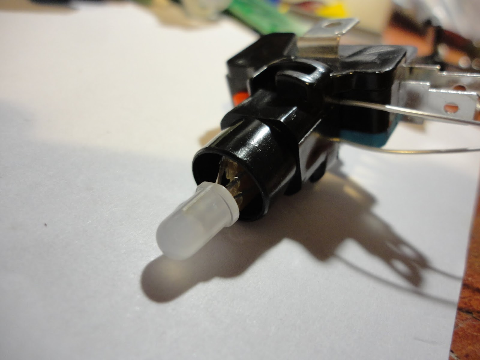
I bought the switches quite a long time before I really decided exactly how I was going to use them. They have translucent white plungers with an LED holder in the microswitch clip at the base. The supplied LEDs were white and resistored up for 12V (I guess as a drop in replacement for filament bulbs in arcade machines). I decided to replace them with RGB LEDs, but I needed to make sure I had a decent scheme for doing this, since I needed to wire up 80 of these switches and didn't want to end up making the same mistake 80 times!
12V LED modules and sockets
Microswitch heaven!
What I ended up with was breaking a matrix board into little squares, so I could thread the leds of the 5mm RGB LED through the holes and slide the board into the socket in place of the white LEDs modules. This worked nicely to connect the common anode and one of the cathodes to the LED socket. I was then faced with somehow getting a connection through to the other two cathodes while not interfering with the operation of the switch.
I have a big roll of Kynar wrapping wire that comes in very handy for this kind of thing. Kynar wire is a single core wire with a very thin insulation layer, so it easily gets through the tiniest of holes and gaps. I could solder two wires to the remaining LED cathodes and thread them down through the socket and out between socket and switch. Since the thin single core wire can be brittle I used little blobs of superglue to anchor the ends after soldering (Its amazing how much more useful superglue becomes if you get a spray can of activator, which sets the glue off instantly - even in blobs)
I am driving my LEDs with LPD6803 chips, which I have a big batch of from an eBay bargain. These are chainable 3-channel, constant current, self-running PWM controllers with a 2 wire serial interface. They allow 5 bits per channel of PWM resolution (Maybe the 8-bit PWM WS2801 would have been better, but I think these LPD6803's are good enough, and they are what I had)
Every single LED needs its own controller chip... thats 80 chips... how to fit them all in? I considered putting an LED driver board on every button but quickly decided that wasn't going actually to make life any easier. In the end I decided to put 8 driver ICs on a PCB and have one PCB per grid column (so 10 boards). There would be a lot of wire in there, but it seemed the most straightforward way to build it.
I've recently started getting small batches of PCBs made up by a supplier in China (ITEAD), and these driver PCBs are only the second batch I have ordered. Just getting the thing wired up to see if it worked (or if I had badly messed up my PCB design) took a long time and the suspense was killing me - but finally I was able to connect up an Arduino to send some data to it... and it worked!!
As well as the 8 x LPD6803 chips the PCB contains a 74HC165 parallel input shift register for reading the switches. I wasn't going to count my chickens until I'd also tested the input part. Wooo, that worked too! (Eventually the input and output driver chips for all the boards will be chained together so the last test will be whether that all works)
The console for the grid is laser-cut 5mm acrylic. I had considered making a box completely out of acrylic, but wondered how sturdy it would be. Eventually I settled on building the box into a flight case and thought cases designed to house 19" rack-mount mixers would be perfect. The one I got is a Reloop case from eBay, where if cost about £75. Not the cheapest way of getting a housing, but it should be good for a few knocks.
So... looks like I have a lot of wiring to do! I am still not certain how I will drive it when its finished, but most likely I will use an Arduino.
I've wanted to make a
“globe POV” for a while after seeing a totally amazing hi-res one
on YouTube a while back. The mechanical side of it (motor drive and
power supply) always put me off a bit – while I think I can design
a PCB and feel pretty confident it's going to work, motors, gears and
bearings are still a matter of kludge and guesswork for me.
I decided to make a 24
LED proof of concept project using the largest size board my free
version of EAGLE would let me work to. I originally intended to use
0805 SMT LEDs mounted on their sides but when I realised what a bitch
they are to solder like that I decided to go with good 'ole 3mm thru
holes of which I have – ahem – about 3,000 blue ones (don't ask).
The electronics was
pretty straightforward – since I have made a few similar things
before (basically this was an Arduino project with a custom designed
PCB) The 24 LEDs are driven by 3 x 74HC595D shift registers through
100 ohm 0805 resistors. I used an Atmega328 in QPF32 package with a
miniature (Nano styley) resonator.
I usually use an FTDI
USB-TTL serial lead for in circuit programming, so I simply added
pads for the the six ICSP connections I needed for burning the
bootloader and temporarily soldered wires to them. In the past I have
routed in a proper 2x3 ICSP header but I don't think I'll bother any
more - after all, burning the bootloader is a one-off procedure and
routing in the header is a pain.
The board is single
sided FR4. After etching and drilling it I tinplated the tracks (I do
this with all my boards now as it makes soldering easier, looks
cooler, doesn't take long, and isn't so expensive). After adding the
wire jumpers to the back I worked in stages to add the components and
test things.
I think its always a
good idea to test at each stage in case you need to junk the board
due to a design problem. First I soldered in the Atmega and the
resonator and burned the bootloader. When that worked I added the
serial programming header, diagnostic LED and resistor and made sure
I could get sketches to run on the Atmega. Only then did I add all
the other components when was confident the brain was alive. I
soldered all the components with an iron, with the exception of the
resonator where I put solder and flux on the pads and used a hot air
tool make the joints.
The rest of it I made
up as I went along, convinced it might go wrong at any moment. I
shaped the board to a disk with a stanley knife, steel rule, pliers
(for snapping) and sandpaper (for smoothing). Then I added in the
slots, top and bottom, to accept a 2mm drive shaft using my new
diamond edge cutting disk on my Proxxon table saw (in retrospect this
blade is fricking awesome and I should have used it to cut out the
circular PCB... you live and learn).
Aligning the 2mm drive
shafts top and bottom was pure guesswork. I both soldered them and
used copious quanitites of cyanoacrylate superglue (with activator
spray) to hold them in place, with the help of a couple of plastic
hub wheels from a model kit supplier.
The drive shafts go
through miniature model bearings in my crudely fashioned frame (made
from MDF I salvaged from an old CD rack, cut with a plain old Bosch
jigsaw) and at the bottom there is a simple reduction gear from a DC
motor to drive it. There is a crude joinery job holding it all
together - I am not proud of it,
What I am more pleased
with was the electrical transfer method I used. In a previous project
I
“borrowed” (saw it on a Youtube video) the idea of using an
axially mounted, graphite-lubricated, 3.5mm jack plug/socket
connection to take power to the rotating LED board while also acting
as a bearing. This time I used some chunky graphite brushes (intended
for drill equipment I think) and drilled a 2.5mm hole in each and
passed the 2mm drive shafts through them, then crudely superglued the
end of the brush springs to my frame. And it worked! In fact it works
rather well and I think I will be using this approach again.
As I expected, some
balancing was needed. I superglued a couple of nuts to the back of
the board to counterbalance the LEDs on the opposite edge. Its not
perfect but it was a big improvement.
I saved soldering the
Hall Sensor until the board was mounted in the frame, so I could make
sure I cut the legs to the right length. A small Neodymium magnet
triggers the sensor.
In hindsight it might
have been better to somehow mount the magnet on the front of the
frame (opposite the vertical part of the frame, so 180 degrees around
the axis from where it is now). The reason is that when the sensor
passes the magnet, a new drawing cycle starts. So this is the point
where the previous draw cycle might be ended early or overrun
(depending on rounding errors due to the timer resolution and
variations in spin speed). With the position of the magnet in my
design these display “glitches” happen right at the front of the
globe and are quite easy to see – it would be better to hide them
around the back by moving the trigger point through 180 degrees, or
by placing the Hall sensor on the same edge as the LEDs rather than
opposite them.
There is a voltage
regulator on the board and I power the motor and board from a common
supply of about 10 volts. Something that surprised me was that when
plugged the USB lead in to the programming header on the board, the
motor received power and span up. I didn't think the current could
cross the regulator in the opposite direction so it was a bit of a
nasty suprise (and presumably it does the regulator no good either).
A 1N4001 rectifier diode on the +10V supply going to the board brush
solved the problem. I was very glad I found this issue before the
motor was attached to the frame or I could have smashed the board.
When it was all fitted
together I tested it out with a simple set of vertical and horizontal
lines, rendering as a wireframe globe, and it looked great. Next I
wanted to display a pixellated map of the world... to get this done I
found a suitable Mercator projection image on Google images and
resized down to the target 24 x 64 pixels in PaintShop Pro (still my
drawing tool of choice for its easy work with small bitmaps). Quite a
bit of manual tweaking was then needed to get a decent recognisable
monochrome image.
The next step was to
calculate the bitmap values to insert in the code. I needed data as 3
bytes for each vertical scan column through the image (64 x 3 bytes
of data) and I needed the low bit positioned at the vertical top of
each byte.
I usually use a
spreadsheet to do this kind of thing (OpenOffice). I wondered how I
might import the mono bitmap image data directly into the
spreadsheet, but as I was in a hurry and the image was small I just
retyped it manually. To help keep track I divided the image into 8x8
squares and highlighted them chessboard fashion in yellow. This meant
I could work one square at a time and it only took 15 minutes or so
to enter the data into the spreadsheet and use formulas to calculate
the bitmap values I needed.
I copy/pasted the
values from the spreadsheet into the Arduino sketch, programmed the
globe and fired it up – and it worked first time! The Pacific
looked a bit empty though, so I went back and added Hawaii.
I put a 32kbit I2C
EEPROM on the board so that I can store a decent set of image data to
make animations possible. I haven't done anything with it yet.
Here is a brief
description of how the code works. Almost all the POV projects I've
made work in this way...
The sketch sets up the
Atmega328's internal timers 1 and 2 to run at the same rate (1/64 of
full clock speed). This means they are counting at a very high rate
(I think it works out as 62500 counts a second).
The sketch uses
“interrupts” – an interrupt is a way for a specific hardware
event (like a pin changing value or an internal timer reaching a
certain threshold) to cause a specific piece of program code (called
a “service routine”) to be run immediately. This means the
program does not need to keep “polling” things like inputs and
timers, which would not be very accurate at these timescales.
Interrupts are really the only way to get the consistent timing
accuracy we need.
We use two interrupts,
one is called when the hall sensor fires and the value on pin 2
(Interrupt 0 pin) changes. The service routine for this interrupt
captures the value of timer 1 and resets the timer. This value is the
number of timer ticks in one complete rotation of the board.
Now we divide this up
to get the number of timer ticks in a single “sector” (vertical
scan column width). Although there are 64 columns in the image, I
actually insert an artificial blank column between every pair of
image columns to cleanly seperate the “pixels” rather than
letting them run together into streaks (it just looks nicer) so I
treat the image like it has 128 columns.
So the timer count is
divided by 128 and the result is put into the timer 2 “period
register”. Now when timer 2 reaches the value of the period
register it is automatically reset and another interrupt fires. The
service routine for this interrupt will therefore get regularly
called 128 times on each revolution – perfect! Now we just need to
load values from the image data into the LEDs. We need to keep a
count of how far round the revolution we are and we can add an
incrementing offset to make the image appear to spin. It is also here
that we turn off all the LEDs on every other call to add the gaps
between the pixels.
The LEDs are loaded by
simple shift register stuff (Check the Arduino tutorials if you don't
know what a shift register is) . Speed is of the essence, so the
three shift registers are loaded in parallel using 3 data lines and
common clock lines. I avoid using digitalWrite() to drive the output
pins on anything like this and go direct to the port registers since
it's an order of magnitude faster!
At the BuildBrighton hackspace we have a workshop planned for DIY stompbox builders. We'll probably be concentrating on a Fuzzface clone since thats nice and simple. Just to make sure we knew what we're doing we put together a couple of Fuzz face circuits last week, and they worked!
Inspired by this, and being a lover of the Line5 "Fuzz Pi" (Emulation of the Electro Harmonix Big Muff Pi) model for bass and guitar, I decided to try to make a Bigmuff clone of my own - complete with a proper case et al. I worked from (and fully credit) the following online schematics
I also added a bypass and a three-state indicator LED showing "standby" (guitar connected, effect bypassed) as a dim glow and "on" as a bright glow (just with 2 different series resistances). This needs a 3PDT switch.
I was pretty pleased with the result... a nice edgey fuzz with enough bottom to work well on a bass (my main instrument)
Mikepea at BuildBrighton is building a Scalextric setup with a difference! One of the many features we're thinking about is a POV display on the roof of a car which will plot out a graphic image as the car moved round the track. The first test was to see if the concept would work (basically are the cars fast enough to get a decent POV effect?). To try this out I made a quick little POV circuit on a 1" square of flexible copper clad. There is a PIC16F688 directly driving 10 green LEDs and there is no trigger or synch on it (it just runs continuously)
For the first try we opened up a car and took our power from the +5V and GND pads of the programming header on the Digital Scalextric controller board inside the car. This seemed to power the POV board fine but the car itself would not work. Unfortunately it still didn't work when the POV was removed... oh crap! not sure exactly what happened there, but Mike was very good about it and offered another car...
Worried about frying another car, we took a different approach this time and added our own voltage regulator and smoothing caps, taking power directly from the diodes that rectify the AC being picked up from the track. We only had a big 7805 regulator to work with, but actually it looks pretty cool stuck to the hood with a couple of caps. Very 1970's hot rod.
More importantly it worked.. that is until one time the car rolled and the POV circuit on the roof seems to have got a zap directly from the 12VAC on the track and the PIC died, leaving all 10 LEDs jammed on. Insulation is obviously something to consider for the next time!
So was the concept proved? it seemed to work pretty well - especially on long exposure photos. I had it displaying some particularly peurile text, but it would probably work better with small graphical images...
I thought it was about time to give an update on the MIDI ping pong table sensing stuff. I've spent quite a lot of time on it, been through a few iterations of the hardware, and learned a lot! I started this as a total newbie as far as analog electronics go (Op-amps etc) and now I think I have at least grasped a few basic techniques. I'd like to try to share the lessons I learned, but I'll warn you now that you'll need to be quite interested in this stuff to get through this post :o)
Going back to the start, my first sensing attempt was to use piezo sensors and an unbuffered inverter (4069) as an amplifier (an idea picked up from Nicholas Collins' book 'Handmade Electronics Music'). I fed the amplified signal into a Darlington transistor which I hoped would give be the logic "hard edge" signal I needed for my timing code. The result was very sensitive, however there were a few things going on that I didn't understand (sometimes the output of the transistor seemed to oscillate without any input). At the time I seemed to be picking up a lot of electrical noise and became convinced the amplifier circuit needed to be closer to the piezo sensor.
My second iteration used a proper op-amp (An LM358 configured for single supply) which was placed close to the piezo sensor. The circuit was still very sensitive but the "noise" problems thankfully seemed to have gone away. I tried feeding the output of the op-amp to a digital input pin on a PIC but I was finding that the when a pulse was detected the digital input would trigger not just once, but many times over microsecond timescales and this would cause problems for the code (e.g. pin change interrupt fires but the pin state does not seem to have changed)
At the time I didn't fully understand the reason for the digital input state flipping about like this and could only assume it was some kind of high frequency harmonic component of the actual vibration being picked up (now I know better... see below). However I needed to do something about it so that my microcontroller code would have a decent length pulse it could detect reliably. I added a 555 circuit configured as a "retriggerable monostable" (this was something I read about online). Basically once the first ON pulse come into the 555, no matter how fleeting, the 555 will hold the output HIGH for a controllable timed period, so all the spurious follow-on pulses are masked and we don't need to care about them. The output became nice and clear for the interrupt pins on the MCU and worked reliably.
So by now I had an LM358 and a 555, plus a bunch of caps, diodes and resistors, that I wanted located right up close to the piezo sensor. I decided to make the circular surface mount boards shown in a previous blog post. I suspected at the time they might be a bit over-engineered, but as long as they worked I didn't care.
Then I started focusing on the triangulation code and noticed occasional inconsistencies in the sensor timing readings, which I became convinced were due to the differential input levels at which each sensor fired. This makes sense because the "front" of the sound rippling out over a table top is not a hard vertical edge, but rather a slope, with the vibrational displacement ramping up from zero to to its maximum as the wave passes under the sensor. The level at which the sensor "triggers" will depend on its own sensitivity level, but not all 4 sensors will have exactly the same trigger levels. Now, since the speed of sound in dense wood is very high, a small difference in trigger level might translate to a big difference in the calculated position. Damn!
I was helped here by Matt Waterman, who got in touch with me via my blog and suggested using zero crossing detection as a solution to this. My understanding here is that once the initial wave front passes the sensor and triggers it, the vibrational displacement will reach a positive peak, then fall down to to zero, then reach a negative trough before repeating. At some point the displacement it crosses the "zero" value, and this is a distinct point in time which can be detected without the same sensitivity difference issues (since we're comparing positive level with negative level, not two different positive levels, this can be detected more accurately). Since the positive wave front should have the same front-to-back width across all the sensors, the zero-crossing time measurement should be just as suitable for my purposes as a hypothetical perfect measurement of the arrival time of the wave front (becaise we're working with relative time of arrival at the sensors, not the absolute times of arrival)
To work with zero crossing I had to remove the 555 from the circuit (since this masked all the input after the initial wave front triggers the sensor, including the initial zero crossing point). I added an LM339 comparator configured for zero crossing detection (based again on internet research), so the Arduino needed to receive digital inputs from the initial pulse (The Op-amp output) and the zero crossing pulse (the Comparator output). The first zero crossing trigger after the wave front trigger would be the point in time we'd be interested in. With the 555 gone, I was of course back with the issues of the crazy pulse trains that it had been hiding from me... Double Damn!
After more headscratching, Googling, breadboarding and staring at my old CRT oscilloscope and a USB logic analyzer, I tried putting a Schmitt trigger inverter IC in there and Hey Presto!... a perfect clean pulse.
Now if I'd done this before I would have reached for the Schmitt trigger IC right at the start, but this is all a learning curve, and this was one of the most useful things I learned: When forcing an analog level to a digital level use a Schmitt Trigger! All I'd ever used them for was to make oscillators (like Ray Wilson's excellent WSG noisebox)
So how does the Schmitt trigger IC help? Well a trace I got from my USB logic analyzer showed what was going on... Think about an analog sine wave being forced to a digital pulse wave. Now, if you simply connected the analog level to a digital pin you'd expect that above a certain threshold the digital level is HIGH and below the threshold the level is LOW right? This is mostly true, but the problem is that round about the threshold level, on the up or down slope, the digital value goes crazy... it flips *really* fast between HIGH and LOW because its in a "grey area" - it really doesn't know if it should be HIGH or LOW and tiny fluctuations and noise push it one way and the other. This goes on until the input voltage changes enough to get out of this fuzzy "no-mans land" range and we get a stable HIGH or LOW
However, stick a Schmitt trigger in there and there now there are TWO thresholds - one for the rising level and one for the falling level. In the no-mans land between the two, the output of the Schmitt trigger does not change. The result is a nice clean LOW - HIGH - LOW transition. The grey area is gone.
With a Schmitt trigger, the zero crossing worked! And it worked even with a long wire between the Piezo sensor and the op-amp, so I could put all the electronics on a single board and for all sensors. Not only that, but the direct Schmitt trigger output was now working just as well for timing as the zero crossing comparator output! Removing the comparator now simplifies the whole thing and halves the number of digital inputs needed to read the sensors. Result!
So, after that long journey I learned quite a lot. If you managed to read this far I hope it helps you too. I would also say never underestimate the value of an oscilloscope - even a battered old CRT one like mine. For digital stuff a cheap USB storage logic analyser (I used a SCANLOGIC built from a 40 Euro kit) is also invaluable for seeing whats going on in that crazy world of the microsecond timescale.
So, my design now reads 8 piezo sensors (4 for each corner on side of a ping pong table). The sensors are simply wired with screened cable to a central amp box. This has 4 LM358 dual op amps (one channel per sensor) which are now on a 5V dual supply (from a nice board from Futurlec that generates a stable and noise-free bipolar supply from a single input supply). The op amp outputs go through a pair of 74HC14 hex Schmitt trigger inverters and from there to digital inputs of an Arduino Nano.
The Nano uses interrupt on pin change to simply flag the change of pin state, so that a flag can be polled instead of the port input (in case there is a rapid change and a signal is missed). There are two state machines running timing impulses from each side of the table, and the conversion of time-of-arrival information to coordinates is done using the fast approximation approach I described before.
The Nano drives a set of diagnostic LEDs - 8 green LEDs representing the sensors and 2 red LEDs which light when there is a misread (not all sensors firing together on that side of table). The coordinate is mapped into an 8x8 grid and sent out as MIDI using the following encoding method:
MIDI note = 16 * row + col
where row and col are 0..7
The two sides of the table are split into two different MIDI channels. These are to be fed into a second Arduino which does some processing of the raw notes to create a more interesting set of MIDI notes and controllers based on some "intelligence" about gameplay (e.g a "rally" is made up of notes alternating between 2 sides of the table and finishes when there are 2 bounces on the same side or no bounce for a timeout period). The MIDI output from the second Arduino will be used to drive a synthesizer to create the eventual sound of the game.
The note mapping scheme described above is (deliberately) the same as that used in the Novation Lanunchpad. Using MIDI-OX to route MIDI inputs to outputs, this means I can use a pair of Launchpads as a handy display to indicate the detected posiiton of a bounce. It also allows me to use a pair of Launchpads in place of the table while testing the MIDI engine on the second Arduino. I can just alternate pressing buttons on each Launchpad and it things there is a rally going on!
Well, without too much pain, its just about working!
Here is how I went about it, which might help you if you want to make one yourself...
When you pick a drive to use, make sure it has four conductors going to the motor ("Y configuration") rather than three ("Delta configuration") if you want to use the TDA5140A/TDA5144 to drive it. The conductors are likely to be on a tiny flexible ribbon going into the motor on the back of the board.
Get yourself a proper Torx driver to take out the screws holding the drive together (you can work around it with other things but you will drive yourself crazy). Remove the PCB from the back, being careful not to damage the ribbon going to the motor. Remove the metal front cover, remembering that there are usually a few screws hidden behind labels. Less brute force, more patience :o)
Remove the head and magnets by taking out screws. Take out the central screw of from the hub and take off the platter. You might be unlucky and have a platter which sits very low to the backplane. You might need to improvise to jack it up a bit to leave space behind from the leds, or you could combine parts from a couple of drives (as I did) to get the best combination. Another thought is to cut windows for the LEDs in the aluminium backplane, but that seems like a lot of effort!
My replacement platter was cut out of FR4 single sided copper clad board using a 70mm holesaw. A smaller holesaw (19mm I think) was used to cut out the centre, which was then filed to snugly fit the hub of the 2.5" laptop drive. The digits were actually laid out in EAGLE (PCB designer) since it was the only package I had to hand which let you type in rotation angles for characters. This worked OK, but a decent vector drawing package will have more interesting font options. The platter was etched just like a PCB.
It was challenge to fit LEDs and section dividers in the few mm of room behind the platter. My solution was to use SMD components and mount them on flexible kapton copper clad board (awesome stuff) which I picked up on eBay. Just press and peel and etch it as a normal PCB. The finished result, with components on, is only a mm or two in height and can be shaped with scissors and a knife, then glued down in the space under the platter. I made the light dividers from a bit of card cut with a knife and glued to the flexible board.
To index the rotation I used a reflective surface sensor (Osram SFH9202) which detects the passing of a piece of white paper stuck to the back of the platter. I used a strip of matt black insulation tape to give decent contrast on the rim of the platter (FR4 is a bit shiny).
I was a bit worried that the sensor seemed to be getting hot. I am still not convinced this is right, but looking at the data sheet they do dissipate 80mW, and I tried 3 of them and they all did it, so maybe this is right (it hasn't blown up yet!)
The sensor output is quite "analog" and doesn't, by itself, give a nice sharp switching signal. I should have shopped more carefully since Osram do the same sensor with a built in Schmitt trigger output. Still, I had some CD40106 Schmitt trigger inverter chips so I used one of those to give me a clean logic output and it seems to work fine now.
The main board was designed in EAGLE and etched on SRBP using some cheap toner transfer film from a chinese ebay shop. This film is great! it works better than the much more expensive press'n'peel blue and seems less fussy about your ironing technique (i have none). Another first was to etch this with Hydrochloric Acid and Hydrogen Peroxide mixture rather than Ferric Chloride. It is very fast and resulted in less erosion of tracks under the toner, but it also resulted in a nasty lingering chlorine smell pervading the house.
I really enjoy working with SMDs these days, but I used to be terrified of them. Those tiny surface mount components have many advantages: They tend to be cheaper, your boards can be much smaller and need less drilling, and the result is actually really satisfying. I'd say the most important things are magnification (I use a 10x loupe) a decent iron with a small tip (e.g. 0.4 or 0.8mm needle tip), fine solder (e.g. 0.015"), tweezers and a flux pen. Most important of all is practice and expecting it to all go wrong at least a couple of times before you get on a roll with it. Then you'll never look back :)
I'll admit I used solder paste for a couple of the components (the LEDs and their resistors, the two tiny resistor networks, the 16MHz resonator for the Atmega328). I used a hot air tool to reflow the paste. Everything else was done with an iron. The LEDs, resistors and small caps are 0805 size.
I have a small stock of M41T100 realtime clock chips in SOIC8 packages (from an ebay bargain) and I used one of these on this project, with a backup battery.
The MCU is an Atmega328 set up with Arduino bootloader. The code is all Arduino stuff. The Arduino drives the LEDs through a ULN2803 transistor array, since these LEDs are powered in groups of 3 and draw something like 30mA each, which would be too much to drive directly from the Arduino digital output pins.
Last but certainly not least, the hard drive motor is driven by a TDA5144. A word of warning - Don't think you can put power to a hard disk motor and it will spin. These are brushless motors and need electronics to make them work. If you want to try any HDD motor project I recommend you invest in a special IC for it. The Philips TDA5140A and TDA5144 have been perfect for the job in my experience (The TDA5140 - without the A - seems more finicky to get working). You can certainly make your own brushless DC motor controller, but that is a project by itself and I prefer to jump in with the fun stuff :)
Something I was glad I did was to add isolation jumpers to the board so I could power up the Arduino stuff without the motor starting, and vice-versa.
Just starting this project, which again uses a 2.5" laptop drive.
Last year I made a POV "slot" clock on a HDD platter, inspired by other peoples projects I saw online. Around the same time saw an excellent project on YouTube where someone had made a digital POV clock by spinning a set of digit-shaped windows, in front of a row of LEDs. By illuminating each LED when the appropriate digit was in front of it, a row of digits can be displayed... aka a digital clock (http://www.youtube.com/watch?v=7Qyawcw-ots)
That project used a 3.5" drive and it looked like the digits were actually laser or plasma cut into the metal platter itself. I decided to make an easier version by etching the digits into a piece of FR4 copper clad board to replace the platter. FR4 (the fibreglass PCB backing material) is quite translucent so it should transfer the light nicely from LEDs placed behind it.
So far I just have the platter made. I am using a 2.5" laptop drive and the space behind the platter is very limited, so I will probably place the LEDs on flexible kapton copper-clad sheet and put a row of windows cut in plastic sheet over the top to stop cross-illumination.
I'll spin the disk using the same TDA5144 circuit I used in the previous project but I'm not sure about indexing yet... there is not really space on the platter to cut a slot for a photointerrupter, and a magnet on the disk (for a fixed hall sensor) would need a counterweight and might not fit. I might try an IR reflective sensor here, but need to play with them a bit first as I've not used them before.
I picked up a few faulty laptop drives cheap on ebay to take to bits and use for POV projects. I haven't finished them yet, but have been tinkering over time and will post my progress as I go.
For the first one I wanted to put a row of SMD LEDs on the platter itself (or at least on a bit of PCB replacing the platter). The problem is powering the thing... I still need to play with inductively coupled coils for power transfer, but for now I decided to use batteries.
With CR1216's and 1117 regulator
I started with a couple of CR1216 cells in holders - they balanced pretty well when the disk span up and it didn't vibrate too much. Unfortunately when I built up the rest of the circuit I hit a problem.. the LEDs would start up fine but after a few seconds they had faded down to nothing. Fresh batteries - same thing.
CR1216's are 3V lithium batteries (putting out about 3.3V) so I had a 1117 5V regulator on board to give me 5V for the PIC16F688 and the LEDs. I wondered if the current draw was reducing the battery EMF right down below the drop-out voltage of the reg so basically nothing got through the regulator. However when I removed the regulator from the circuit exactly the same thing happened. I guess CR1216's just don't have the oomph for running these high power LEDs :o(
Then I removed the CR1216 holders and put a couple of LR44 holder in their places. LR44's are alkaline button cells at 1.5V and they are a bit bigger than the CR1216's so I worried a bit about their mass on the spinning disk, but it seemed I could get away with that and they didn't fly off or anything (well, maybe just the once..)
The other concern was the lower voltage. I would get 3V instead of 5V to power the LEDs, so would they light properly? They did :o) However, the 3144 hall-effect switch I was going to use for indexing needs 4.2V minimum so I could not use that. Therefore I am currently able to get some pretty, but not stable, patterns while I wait for some new hall switches to arrive (with 3V minimum supply).
With LR44's and reg removed
Once I have the new hall switch I should be able to index the position of the disk using a magnet fixed below it, then I want to display text on the platter. This is really a test... the PIC doesn't have the memory to do much and the batteries probably wont last that long, but I hope to make another with external power (either with a brush to the back of the platter - there is continuity through the hub which makes that easier - or by inductive coupling)
This clip shows it in action. The data is just a binary counter for something to display, but its pretty
A while back I did a "midi conversion" of a couple of Stylophones (The original analog model). I did this by removing the Stylophone electronics and leaving just the stylus, keyboard and resistor ladder. Using the keyboard as a voltage divider its then possible to connect the stylus to an analog input of a microcontroller (such as Arduino) and read the analog voltage to work out which note is being touched, then send out MIDI note data accordingly.
There are a few problems with this approach:
The stylus, keyboard and resistor ladder need to be disconnected from the rest of the stylophone circuitry... Looking at the stylophone schematic the best I could do was a minimum of three connections to break. It wouldn't be possible to have the original sound at the same time as MIDI doing it this way.
As with any mapping from an analog voltage to a range of discrete values there is a risk that a bit of dirt or grime on the keyboard will add enough resistance to cause the wrong note to be mapped. Not good!
Original Stylophones are classic bits of kit and ripping the guts out of them doesn't feel right. Also they aint getting any cheaper.
Since I had a couple of "reissue" Stylophones I picked up on ebay I decided to see if they might prove a better bet for a conversion...
The first problem was getting inside the thing... while the old Stylophone closed with a clip-on back, the new one is glued shut and getting it open without breaking any of the plastic is easier said than done.
Expecting similar nasty cost cutting inside I was actually surprised to find how much is actually in these things. There are no less than four separate circuit boards all individually screwed down to the case and connected with wires (although they are crappy wires with joints that snap when touched)
Removing the boards from the case I found there is the obligatory chip-on-board "black blob" and a few SMD components on the main board. As I expected these new Stylophones do away with the analog tone generator circuit in favour of some custom chip that presumably digitally creates the sound. There is also a through-hole soldered amplifier board and separate carriers for the power/vibrato switches and volume pot.
Those chip-on-board blobs are usually heart-sinkingly unhackable and the sight of one usually spells the end of any thoughts of doing anything interesting. However I was intrigued to see that there was a separate trace from each keyboard pad to the blob, and checking the stylus I found it was wired directly to the +4.5V supply.... so could it be that we had a digital inputs line for each keyboard pad, with some pull-down resistance? That would almost be too good to be true... but true, it was!
So why is that good? well microcontrollers like the Arduino love to read digital (i.e. ON/OFF) inputs. These are nice and reliable without the dirty connection issues of analog inputs, but not only that, you can "piggy back" your inputs off the original input lines (since you are just reading a voltage, not drawing a current). What this means is that you can read the notes being played, while the Stylophone circuit is still attached to the keyboard and playing normally. Also you should be able to get an Arduino to actually play the Stylophone, by feeding ON (logic HIGH) values into the lines... but I might leave that till another day :)
Even better, the board has an exposed pads on each line perfect for carefully soldering a wire to. So thats the good bit. The bad news is that there are 20 of these input lines... thats a lot of wiring and is enough to use up all the inputs on a Arduino board...
I decided to use 74HC165 shift registers to read the keyboard and cut down the number of input lines needed. These chips each read 8 inputs then send the data out in a serial stream. By chaining these together, any number of inputs can be read with just 3 wires to the Arduino (one to "capture" then inputs then a "clock" and data line for reading the data).
Using fiddly surface mount components it was possible to fit 3 of these shift registers on a board that would fit underneath the Stylophone main board, keeping it out of the way and snugly held to stop it shaking around.
An Arduino Nano would fit in the Stylophone case, but I decided to use a custom SMD board since I wanted to add an KXPS5 accelerometer to detect tilt (for pitch bend). I also added another 74HC165 shift register to the chain for reading additional inputs from a row of tactile switches mounted to the back of the Stylophone. A 5mm RGB on the front allows a "mode" to be indicated.
And it worked... mostly. I am having some issues with the accelerometer which may be down to a bad connection (those things are a bitch to solder!) but the keyboard reading and MIDI is working pretty well. Hopefully it will all be finished soon. Watch this space!
UPDATE: I finally found out why the accelerometer wasn't working... even in analog output mode on the KXPS5 it is neccessary to set the "enable" input high only AFTER the chip is powered up (at least 1ms after). I had tied the enable input high on my etched board, d'oh! Failure to do this makes the analog outputs go mental... I only found this out after I decided to ditch my homebrew board and use an Arduino Nano in there.


.JPG)
.JPG)
.JPG)
.JPG)
.JPG)
.JPG)

.JPG)


